Static measurements, Dynamic measurements – Elenco AM/FM Radio Kit User Manual
Page 35
-34-
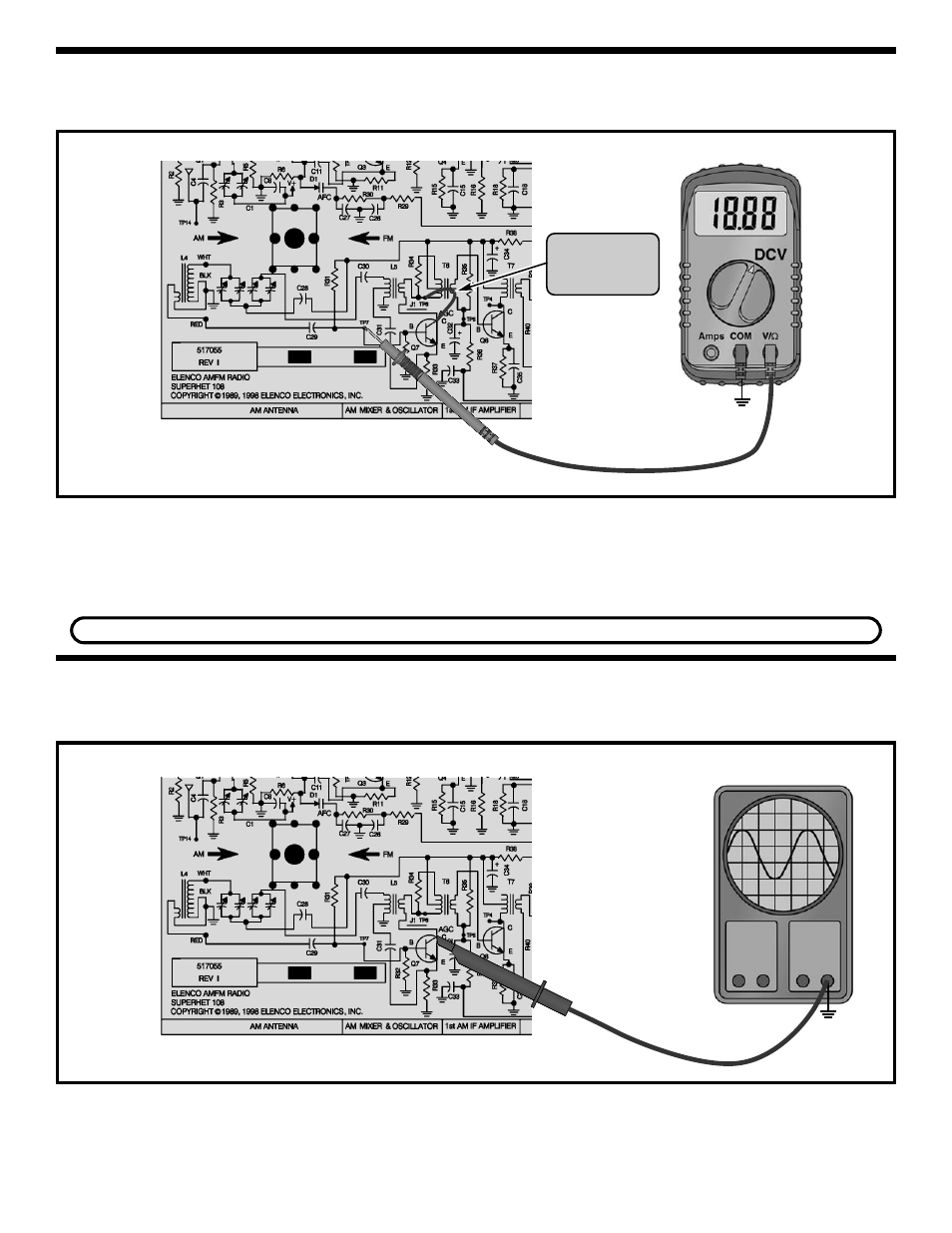
STATIC MEASUREMENTS
Q7 BIAS
Connect your VOM to the circuit as shown in Figure 30.
Figure 31
Figure 30
Connect a clip lead from TP6 to the collector of Q7.
This short prevents Q7 from oscillating. Set the VOM
to read 2 volts DC and turn the power ON. The DC
voltage at TP7 should be about 1.6 volts. If the
voltage in your circuit differs by more than 0.5 volts,
leave the power ON and check the battery voltage. If
the battery voltage is greater than 8.5 volts, check
components R31, R32, R33 and Q7.
Turn the power OFF.
Set the scope to read 1 volt per division and turn the
power ON. The scope should display a low voltage
sinewave. The frequency of the sinewave should
change when the tuning gang is turned. If your circuit
fails this test, check components Q7, gang capacitor,
C28, C29, C30, C31, L4 and L5. Turn the power OFF.
DYNAMIC MEASUREMENTS
AM OSCILLATOR CIRCUIT
Connect your test equipment to the circuit as shown in Figure 31.
Short TP6 to
the collector of
Q7 as shown.
If you do not have an oscilloscope, skip to the AM Final Alignments.
GND
TP15
GND
TP15
Oscilloscope