Elenco AM/FM Radio Kit User Manual
Page 46
-45-
SECTION 7
Figure 42
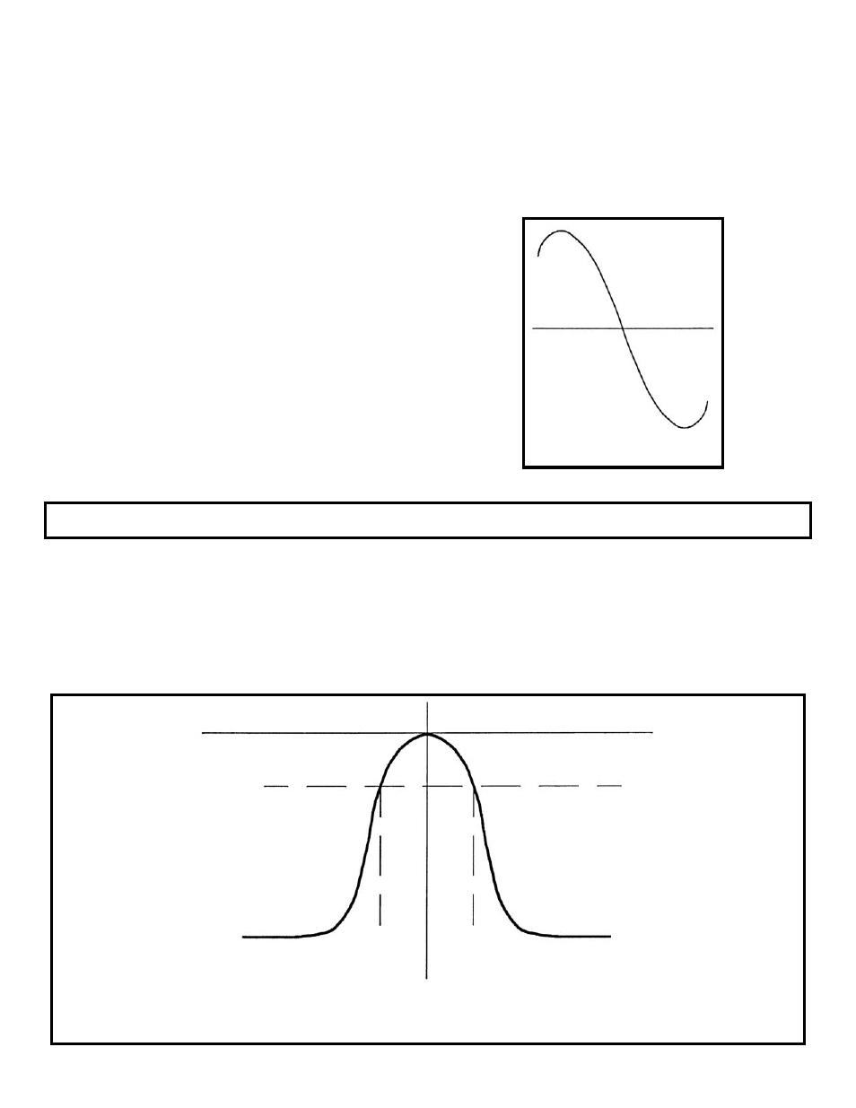
10.625MHz
10.775MHz
10.7MHz
0.707
METHOD #2
ALIGNMENT OF RATIO DETECTOR USING A
RF GENERATOR AND OSCILLOSCOPE
Connect the RF generator and oscilloscope to the
circuit as shown in Figure 40. Set the generator for
10.7MHz modulated at 1kHz, 22.5kHz deviation with
minimum voltage out. Turn ON the radio and turn the
volume control to the minimum. Slowly increase the
amplitude of the generator until a 1kHz sinewave is
seen on the scope. With an alignment tool or
screwdriver, peak the pink coil T4 for maximum
amplitude. Now peak the blue coil T5 for minimum
optimized. Turn the power OFF.
METHOD #3
ALIGNMENT OF RATIO DETECTOR USING A
SWEEP GENERATOR AND OSCILLOSCOPE
Connect the sweep generator and oscilloscope to the
circuit as shown in Figure 40. Set the sweep
generator for 10.7MHz and minimum voltage out.
Turn the power ON and set the volume control to a
minimum. Increase the amplitude of the sweep
generator until an “S” curve is seen (refer to Figure 41).
Using an alignment tool or screwdriver, adjust the blue
coil T5 until the “S” curve is centered, until each half of
the “S” is equal. Repeat these steps until the alignment
is optimized. Turn the power OFF.
The purpose of the 2nd IF amplifier is to increase the
amplitude of the intermediate frequency (IF) while
also providing Selectivity. Selectivity is the ability to
“pick out” one station while rejecting all others. T3
acts as a bandpass filter that only passes signals
around 10.7MHz. The resistor R19 is used to widen
the 3dB bandwidth of the 2nd FM IF amplifier.
The gain at 10.7MHz is fixed by the AC impedance of
the primary side of T3 and the current in Q5. The
current is fixed by R16, R17 and R18. Capacitors
C18 and C17 bypass the AC signal to ground. C20 is
a bypass capacitor from V+ to ground.
Figure 41
SECOND FM IF AMPLIFIER