Dynamic measurements, Am detector and agc test, Figure 25 – Elenco AM/FM Radio Kit User Manual
Page 26: Figure 24, System check
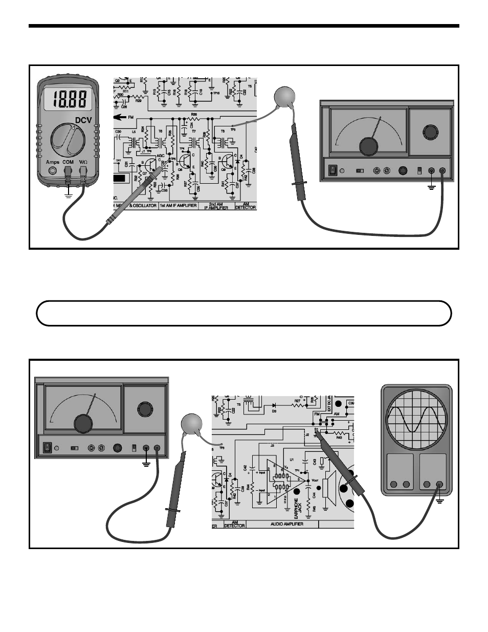
-25-
DYNAMIC MEASUREMENTS
AM DETECTOR AND AGC TEST
Connect your VOM and RF generator as shown in Figure 24.
Figure 25
If your RF generator does not have amplitude modulation and
you do not have an oscilloscope, skip to Section 3.
Figure 24
Set the VOM to accurately read 2 volts DC and set
the output of the RF generator for 455kHz, no
modulation, and minimum voltage output. Turn the
power ON and slowly increase the amplitude of the
generator until the voltage at TP5 just starts to drop.
This point is called the AGC threshold with no IF
gain. Make a note of the amplitude setting on the RF
generator here: ____________.
Set the RF generator at 455kHz, 1kHz at 80%
modulation and minimum voltage output. Turn the
power ON and set the volume control at maximum.
Slowly adjust the amplitude of the RF generator
output until you hear the 1kHz tone on the speaker. If
this test fails, turn the power OFF and check R42 and
D4. Turn the power OFF.
SYSTEM CHECK
Connect your equipment as shown in Figure 25.
GND
TP15
Generator
.001
μ
F
GND
TP15
GND
TP15
Generator
GND
TP15
Oscilloscope
.001
μ
F