Static measurements – Elenco AM/FM Radio Kit User Manual
Page 11
-10-
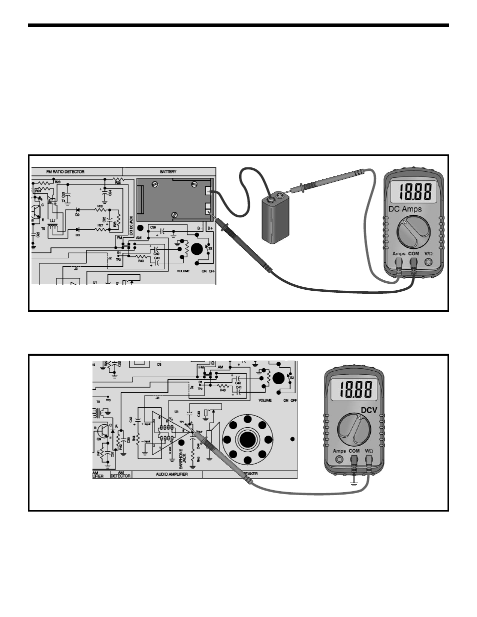
OUTPUT BIAS TEST
Put the battery into the holder.
STATIC MEASUREMENTS
POWER TEST
For all measurements, connect your equipment GND
to circuit GND TP15. Set your VOM (Volt-Ohm-
Millimeter) to read 2 amps DC. Connect the meter to
the circuit as shown in Figure 6. Make sure that the
volume control is in the OFF position (turned fully
counter-clockwise). While watching your VOM, turn
the volume to the ON position (rotate clockwise until
a “click” is heard). The VOM should indicate a very
low current. Adjust your meter for a more accurate
reading if necessary. If the current is greater than 20
milliamps, immediately turn the power off. The
current should be less than 10 milliamps. This is the
current drawn by the battery when no input signal is
present (the “idle current”). Turn OFF the power. If
your circuit fails this test, check that all of the parts
have been installed correctly, and check for shorts or
poor solder connections.
Figure 6
Figure 7
Adjust your VOM to read 9 volts and connect it as
shown in Figure 7. Make sure that the battery, or a 9
volt power supply (if available), is properly connected
and turn the power ON. The voltage at TP1 should be
between 3 to 6 volts. If you get this reading, go on to
the next test. If your circuit fails this test, turn the
power OFF and check that the integrated circuit is
correctly inserted in the correct location. The notch of
the IC must be in the same direction as marked on
the PC board. Check that all resistor values are the
correct value and not interchanged. All static tests
must pass before proceeding to the Dynamic Tests or
the next section.
–
+
+
–
GND
TP15