Elenco AM/FM Radio Kit User Manual
Page 20
-19-
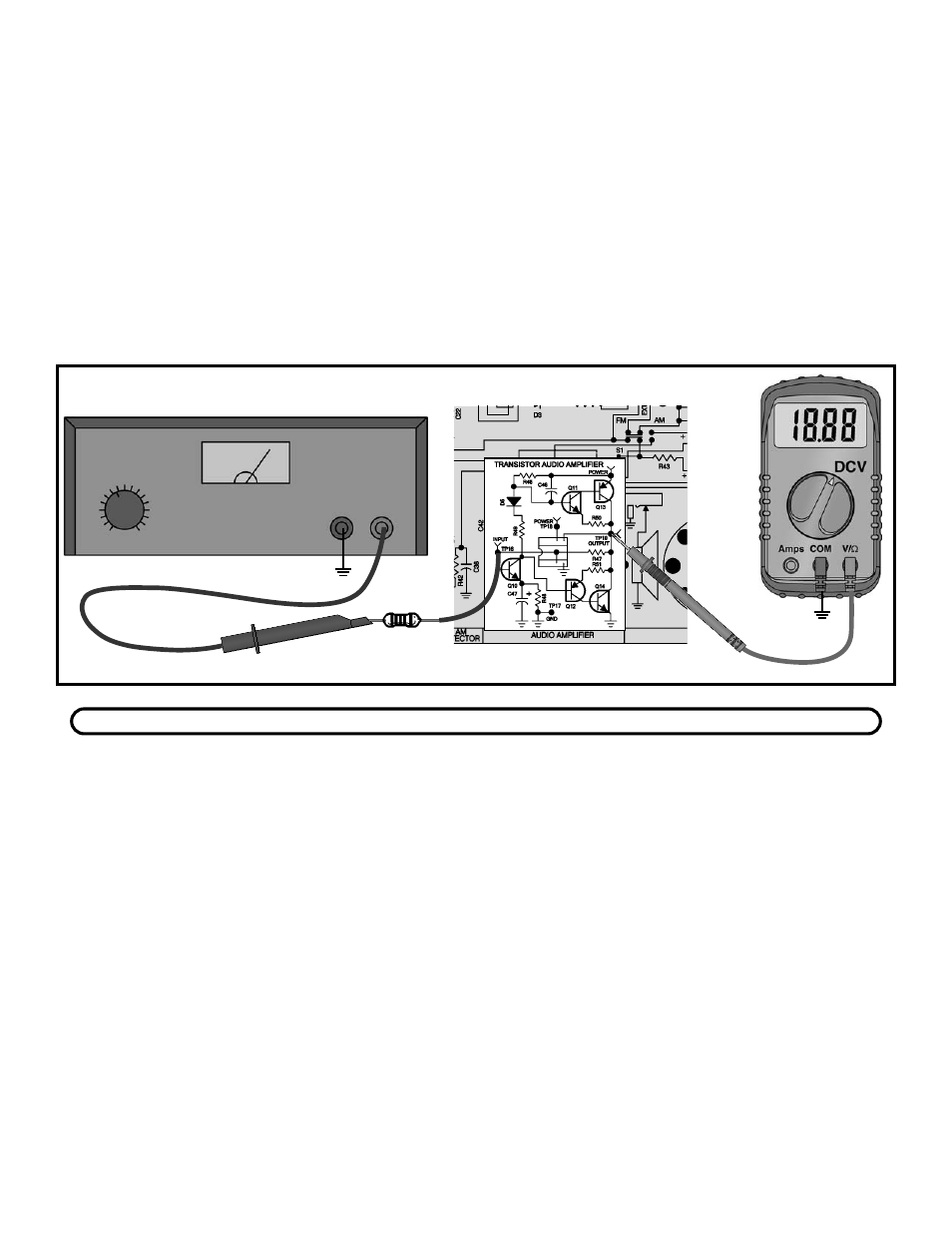
It is advisable to use a digital meter because of the
small voltage changes in the following test. Connect
your VOM to the circuit as shown in Figure 15. Set your
VOM to read 1 volt DC and turn the power ON. Record
the base of Q10 here:
Vb1 = _____ volts.
Now set your VOM to read 9 volts and connect the
positive lead to test point TP19. Record the output bias
voltage here:
Vo = ____ volts.
Turn the power OFF. With a 1M ohm resistor (brown-
black-green-gold), R34, connect the power supply to the
circuit as shown in Figure 16.
Turn the radio ON and turn the power supply ON.
Increase the supply voltage until the voltage at TP19 is
equal to V
o
. Now increase the voltage of the supply until
the voltage at TP19 decreases by 1 volt. Move the
positive lead of your VOM to the base of Q10 and
record the voltage here:
Vb2 = ______.
It may be necessary to change scales of your VOM for
a more accurate reading. Turn the power OFF and
disconnect the power supply. Since the DC gain equals
the DC change at the output divided by the DC change
at the input, the DC gain of the audio can be calculated
as: 1 / (Vb2 - Vb1). Your answer should be near the
calculated DC gain of 47.4.
The AC gain can be calculated in the same manner as
the DC gain except for two differences. For AC,
capacitor C47 bypasses the emitter resistor R48
leaving only the effective emitter resistance, and there
is a resistance seen at the output of Q13 and Q14. The
AC gain of Q10 can be calculated as R46 / Rj or 3300
/ 22.6 which equals 146. When the input signal is
positive, there will be a current flowing in Q11, which we
will call I(Q11). This current will then be multiplied by the
Beta (
β
) of transistor Q13 or
β
x I(Q11). The total
current at the output is equal to I(Q11) x (1 +
β
). The
resistance of R50 is also seen at the output. The
resistance is effectively divided by
β
, R50 /
β
. Assuming
β
of the output transistors are equal to 100 than the
resistance seen at the output is equal to 1 ohm, 100 /
100. This means that there is a voltage divider between
the output and the 8 ohm speaker. The signal is now
divided down so that the output is equal to the AC (gain
of Q10) x (8 / (1+8)), or 146 x (8 / 9) which equals 130.
This is also true when the input signal is negative. The
only difference is that Q12 and Q14 are now
conducting. Connect the VOM and audio generator to
the circuit as shown in Figure 17.
Normally the AC gain is measured at a frequency of
1kHz. Your VOM, however may not be able to accurately
read AC voltages at this frequency. Therefore, it is
recommended that this test be performed at 400Hz. Set
the audio generator at 400Hz and minimum voltage
output. With the power ON, set your VOM to read an AC
voltage of 1 volt at test point TP19. Increase the volume
control about half way. Slowly increase the amplitude of
the audio generator until your VOM reads 1 volt AC.
Leave the audio generator at this setting and move the
positive lead of your VOM to TP16. Record the AC input
voltage to the amplifier here:
Vin = __________ volts.
If you do not have an audio generator, skip the following test and go directly to Section 2.
AC GAIN
Figure 16
R34
1M
Ω
If you do not have a power supply,
use a 9 volt battery instead.
Power Supply
+
–
GND
TP17
GND
TP17