Elenco AM/FM Radio Kit User Manual
Page 32
-31-
The “difference frequency” is used as the
intermediate frequency in AM radios. The collector of
Q7 also contains an IF transformer (T6) tuned only to
the difference frequency. This transformer rejects all
frequencies except those near 455kHz. T6 also
couples the 455kHz signal to the base of Q8 to be
processed by the IF amplifiers. The antenna and the
oscillator coils are the only two resonant circuits that
change when the radio is tuned for different stations.
Since a radio station may exist 455kHz above the
oscillator frequency, it is important that the antenna
rejects this station and selects only the station
455kHz below the oscillator frequency. The
frequency of the undesired station 455kHz above the
oscillator is called the image frequency. If the
selectivity of the antenna (Q factor) is high, the image
will be reduced sufficiently.
The oscillator circuit must also change when the
radio is tuned in order to remain 455kHz above the
tuning of the desired radio station. The degree of
accuracy in keeping the oscillator frequency exactly
455kHz above the tuning of the antenna is called
tracking accuracy.
C28 - .1
μ
F Discap (104)
R31 - 56k
Ω
Resistor
(green-blue-orange-gold)
C30 - 150pF Discap (151)
L5 - AM Oscillator Coil
(Red Dot)
J1 - Jumper Wire
(use a discarded lead)
TP7 - Test Point Pin
(see Figure A)
C31 - .01
μ
F Discap (103)
Q7 - 2N3904 Transistor
(see Figure J)
R32 - 12k
Ω
Resistor
(brown-red-orange-gold)
R33 - 3.3k
Ω
Resistor
(orange-orange-red-gold)
C29 - .02
μ
F Discap (203)
or .022
μ
F Discap (223)
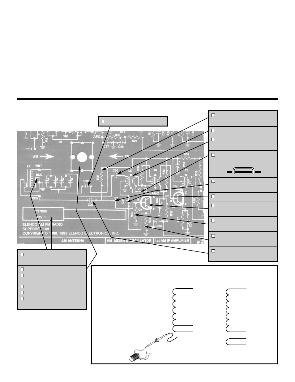
ASSEMBLY INSTRUCTIONS
L4 - AM Antenna w/ holders
(see Figures L & M)
C1 - Tuning Gang Capacitor
2 Screws M2.5 x 3.8mm
(see Figure N)
Knob (dial)
Screw M2.5 x 7.5mm
Label AM/FM
(See Figure O)
Note: Mount the tuning gang
capacitor to the foil (green)
side of the PC board.
White
Black
Red
White
Black
Red
Green
}
}
}
R = 9-11
Ω
R = 1-1.5
Ω
4 Wire
3 Wire
Determine if you have a three wire or four
wire coil. Resistance measurements will be
used to check the configuration of the coil.
Slide one holder off the ferrite core of the
antenna assembly. Then slide the coil off the
the ferrite core. Measure the resistance of
the coil. Your readings should match the
approximate values as shown.
Note: If the end of a wire from the antenna
should break off, strip the insulation off the
end with a hot soldering iron. Lay the wire
down on a hard surface and stroke the wire
with your iron. The insulation
should come off very easily.
CAUTION: The soldering
iron will burn the hard
surface that you
are working on.
}
Figure L
R = 9-11
Ω
R = 1-1.5
Ω