Alignment with no test equipment – Elenco AM/FM Radio Kit User Manual
Page 57
With an alignment tool or screwdriver turn coils T1,
T2 and T3 fully counter-clockwise. DO NOT FORCE
THE COILS ANY FURTHER. Turn each coil in about
1¼ to 1½ turns.
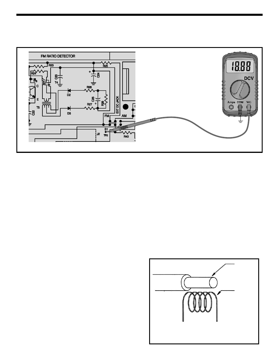
Use the earphone provided for best results. Switch to
the FM position. Connect your VOM to the circuit as
shown in Figure 52. Turn the radio ON and tune the
radio to a weak station. It is best to keep the volume
at a low level. Adjust T1 for the minimum voltage on
your VOM. Reduce the volume if necessary. Adjust
T2 for minimum voltage on your VOM and reduce the
volume control if necessary. Adjust T3 for minimum
voltage on your VOM and reduce the volume control
if necessary. As you adjust the coils you should hear
less distortion and noise. Repeat this procedure until
the FM IF gain is optimized. This process peaked the
FM IF amplifier to their maximum gain.
DETECTOR ALIGNMENT
Adjust T4 for minimum voltage on your VOM. Adjust
T5 for minimum distortion. Repeat these 2 steps until
the ratio detector alignment is optimized.
OSCILLATOR ALIGNMENT
Tune the radio to a known station around 90MHz.
Once a station is found and its broadcast frequency
is known, rotate the dial until the white pointer is
aligned with that stations frequency on the dial. Using
the “magic wand”, place the brass end near coil L3.
Refer to Figure 53.
If the station is heard, this means that L3 needs less
inductance. Carefully pull apart L3 until the station is
heard. Place the iron end near L3. If the station is
heard, this means that L3 needs more inductance.
Carefully press together L3 until the station is heard.
Pulling apart or pressing together L3 just a small
amount will have a great effect on the coils resonant
frequency. Repeat this step until the pointer is
aligned to the station’s frequency. Tune the radio to a
station around 106MHz. Once a station is found and
its broadcast frequency is known, rotate the dial until
the white pointer is aligned with that station’s
frequency on the dial. Place the brass end of the
“magic wand” near L3. If the station is heard, it
means that L3 needs more capacitance. Carefully
adjust the FM oscillator trimmer (as shown in Figure N,
page 32), on the back of the gang until the station
-56-
ALIGNMENT WITH NO TEST EQUIPMENT
IF ALIGNMENT
Figure 53
“Magic Wand”
RF Coil
Spread apart the coil for less inductance
Press the coil together for more inductance
With an alignment tool or screwdriver turn coils T1,
T2 and T3 fully counter-clockwise. DO NOT FORCE
THE COILS ANY FURTHER. Turn each coil in about
1¼ to 1½ turns.
Figure 52
GND
TP15