Am alignment with test equipment – Elenco AM/FM Radio Kit User Manual
Page 37
-36-
AM ALIGNMENT WITH TEST EQUIPMENT
IF ALIGNMENT
Tune the radio for a station around 600kHz. With the
“magic wand” place the brass end near the antenna
coil as shown in Figure 32. If the signal heard at the
output increases, it means that the antenna coil needs
less inductance. To remove inductance, carefully slide
the antenna coil along its ferrite core in the direction
shown in Figure 32. Place the iron end of the “magic
wand” near the antenna coil. If the signal heard at the
output increases, this means that the antenna coil
needs more inductance. To add more inductance,
carefully slide the antenna coil along its ferrite core in
the direction shown in Figure 32. Repeat these steps
until the signal heard decreases for both ends of the
“magic wand”. Tune the radio for a station around
1400kHz. With the “magic wand”, place the brass end
near the antenna coil. If the signal heard at the output
increases, it means that the antenna coil needs more
capacitance. Adjust the antenna trimmer on the back
of the gang until the signal is at its loudest. Refer to
Figure N for the location of the antenna trimmer. Place
the iron end of the “magic wand” near the antenna
coil. If the signal heard at the output increases, it
means that the antenna coil needs less capacitance.
Adjust the antenna trimmer on the back of the gang
until the signal is at its loudest. Repeat these steps
until the signal heard decreases for both ends of the
“magic wand”. Since the adjustment of both the
antenna trimmer and antenna coil will effect the
antenna alignment, it is advisable to repeat the entire
procedure until the antenna alignment is optimized.
This process sets the tracking of the AM radio section.
Once the antenna is properly aligned, CAREFULLY
APPLY CANDLE WAX or glue to the antenna coil and
the ferrite rod to prevent it from moving (see Figure 33).
Cut the shim flush with the antenna.
This concludes the alignment of the AM radio
section. If no stations are heard, verify that AM
signals are present in your location by listening to
another AM radio placed near the Superhet 108. If
the AM section is still not receiving, go back and
check each stage for incorrect values and for poor
soldering. Proceed to the FM assembly section.
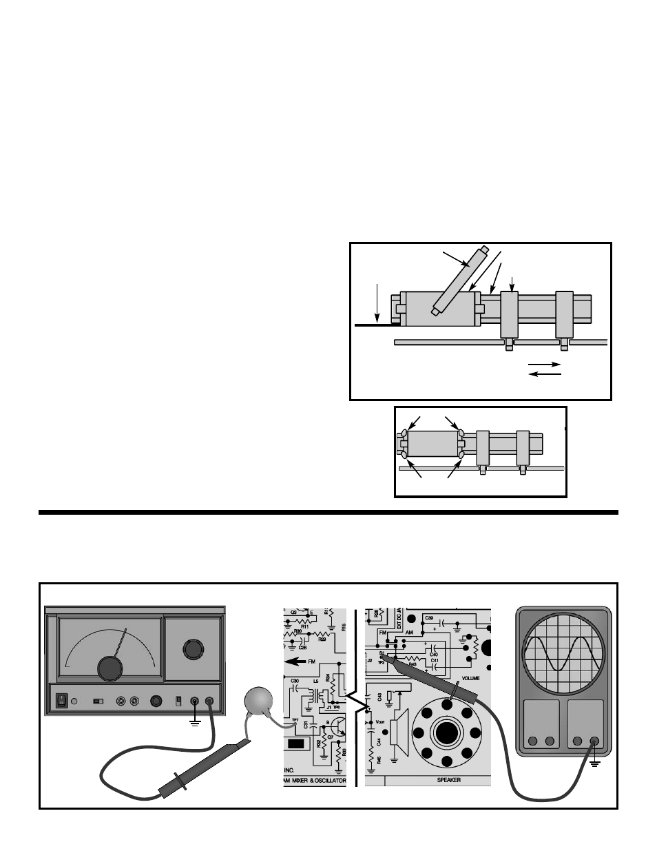
ANTENNA ALIGNMENT
Figure 33
Wax
Wax
Connect your RF generator and oscilloscope as
shown in Figure 34. Make sure that the switch is in
the AM position. Place a short from the collector of
Q7 to TP6. This short “kills” the AM oscillator.
Antenna coil
Ferrite core
Antenna holder
If the antenna needs:
• More inductance, slide the coil
• Less inductance, slide the coil
Magic wand
Antenna
shim
Figure 32
GND
TP15
Generator
GND
TP15
Oscilloscope
.001
μ
F
Figure 34