Static tests, Assembly instructions – Elenco AM/FM Radio Kit User Manual
Page 49
-48-
SECTION 8
FIRST FM IF AMPLIFIER
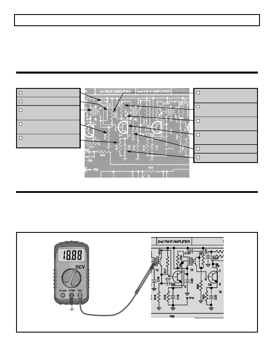
STATIC TESTS
Connect your VOM as shown in Figure 45. Turn the
power ON. The voltage at the base of Q4 should
approximately be 1.4 volts. If you do not get this
reading, check R12, R13, R15, Q4 and T1.
C13 - .01
μ
F Discap (103)
C14 - .01
μ
F Discap (103)
T1 - FM Mixer Coil
(Orange Dot)
R12 - 10k
Ω
Resistor
(brown-black-orange-gold)
R15 - 2.2k
Ω
Resistor
(red-red-red-gold)
R13 - 47k
Ω
Resistor
(yellow-violet-orange-gold)
R14 - 10k
Ω
Resistor
(brown-black-orange-gold)
TP11 - Test Point Pin
(see Figure Q)
Q4 - 2N3904 Transistor
(see Figure R)
C16 - .01
μ
F Discap (103)
C15 - .01
μ
F Discap (103)
Q4 BIAS
Figure 45
The operation of the first IF amplifier is the same as
the second IF amplifier except that the gain is
different. The gain is set by the AC impedance of the
primary side of T2 and the current in Q4. The current
in Q4 is set by the resistors R12, R13 and R15.
Capacitors C14 and C15 bypass the AC signal to
ground. C13 and C16 are bypass capacitors from V+
to ground to prevent feedback on the V+ line. R19 is
used to widen the bandwidth of the transformer T2.
ASSEMBLY INSTRUCTIONS
GND
TP15