Static measurements antenna fm assembly – Elenco AM/FM Radio Kit User Manual
Page 56
-55-
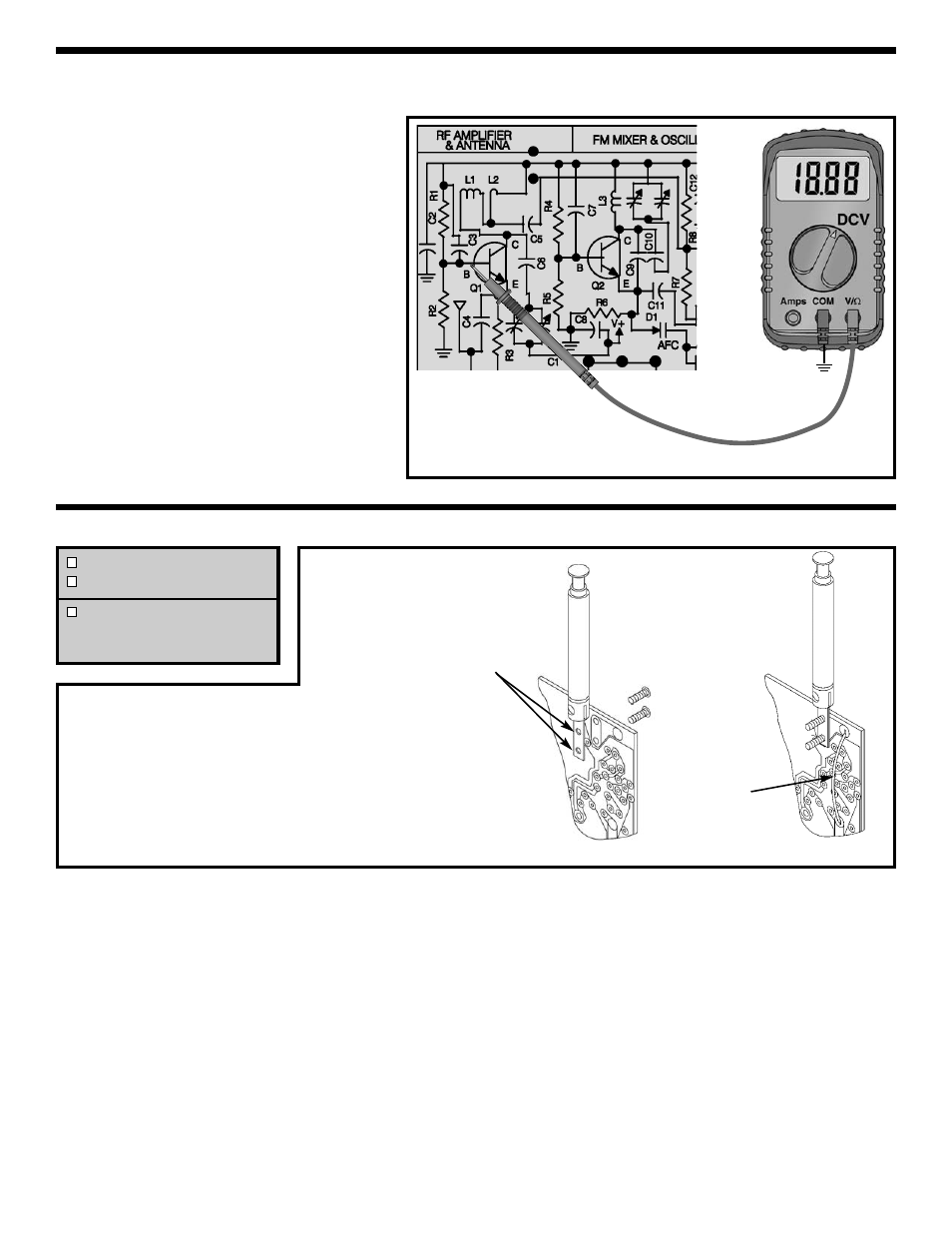
Q1 BIAS
Connect your VOM to the circuit as shown in
Figure 51. Set your VOM to read 9 volts and
turn the power ON. The voltage at the base
of Q1 should be about 1.6 volts. If you do not
get this reading, check R1, R2, R3 and Q1.
Turn the power OFF.
Threaded holes
Figure 51
There are two procedures for the final alignment
steps. The first alignment procedure is for those who
do not have test equipment and the second is for
those who do have test equipment.
Your “magic wand” will be used to align the FM
oscillator circuit and the FM RF amplifier. When the
brass end of your “magic wand” is placed near the
FM oscillator coil L3, the coil reacts as if inductance
has been removed. Likewise, when the iron end of
the “magic wand” is placed near the coil L3, it reacts
as if inductance has been added. The same is true
for the RF coils L1 and L2. When the inductance of a
resonant circuit is changed, the resonant frequency
is changed also.
When aligning the oscillator, changing the resonant
frequency changes the frequency of oscillation.
Likewise, when aligning the RF amp, changing the
resonant frequency at which it was selective.
When aligning the oscillator and RF circuits, coils L1
and L3 will be adjusted at the lower end of the band,
while the oscillator and RF trimmer capacitors are
adjusted at the higher end of the band. This is done
so that the RF amp tracks the oscillator properly.
Solder
jumper wire
Figure W
STATIC MEASUREMENTS
ANTENNA FM ASSEMBLY
Mount the antenna to the PC board with two screws
as shown. NOTE: Some antennas have only one
threaded hole.
Cut a 2½” wire and strip ¼” of insulation off of both
ends of the remaining jumper wire. There are no
holes for the wire in this location, so tack solder the
wire to the pads as shown.
FM FINAL ALIGNMENTS
Antenna FM
2 Screw M2 x 5mm (antenna)
2½” Wire #22AWG Insulated
(extra wire in AM Section)
(see Figure W)
GND
TP15