Rf amplifier assembly instructions – Elenco AM/FM Radio Kit User Manual
Page 55
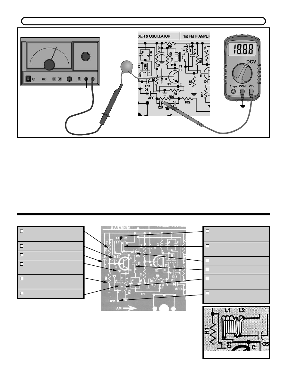
Connect the RF generator and VOM to the circuit as
shown in Figure 50. Set your VOM to read 9 volts DC.
Set your generator at 10.7MHz no modulation and
moderate signal strength output. Turn the power ON.
Record the voltage of D1 here:
V(D1) = ________.
While watching your VOM, slowly decrease the
frequency of your generator. As the frequency
decreases, the voltage at D1 should increase.
Increase the frequency of the generator until the
voltage is equal to V(D1). While watching your VOM,
increase the frequency of your generator. As the
frequency increases, the voltage at D1 should
decrease. This correction voltage is what keeps the
oscillator from drifting. If the voltage at D1 still does
not change at D1, check D1, R29, R30, C26 and
C27. If these parts are inserted correctly and the
voltage at D1 still doesn’t change, then increase the
amplitude of your generator and repeat the same
steps again. Turn the power OFF.
Figure 50
Figure V
R1 - 22k
Ω
Resistor
(red-red-orange-gold)
C3 - .001
μ
F Discap (102)
C2 - .005
μ
F Discap (502)
Q1 - 2N3904 Transistor
(see Figure R)
R2 - 6.8k
Ω
Resistor
(blue-gray-red-gold)
C4 - 470pF Discap (471)
L1 - FM RF Amp Coil
(6 Turns) see Figure V
L2 - FM RF Amp Coil
(2 Turns) see Figure V
C5 - 470pF Discap (471)
C6 - 33pF Discap (33)
R3 - 470
Ω
Resistor
(yellow-violet-brown-gold)
TP14 - Test Point Pin
(see Figure Q)
If you don’t have an RF generator, skip to the RF Amplifier Assembly Procedure.
RF AMPLIFIER ASSEMBLY INSTRUCTIONS
-54-
GND
TP15
Generator
.001
μ
F
GND
TP15