Assembly instructions, Figure e figure f, Figure g – Elenco AM/FM Radio Kit User Manual
Page 10
-9-
ASSEMBLY INSTRUCTIONS
Battery holder
3 Screws M1.8 x 7.5
3 Nuts M1.8
** Solder and cut off
excess leads. **
Volume/S2
(50k
Ω
Pot / SW)
with nut & washer
Plastic washer
Knob (pot)
Earphone jack
with Nut
(see Figure E)
Speaker
Speaker pad
Wire #22AWG insulated
(see Figures F & G)
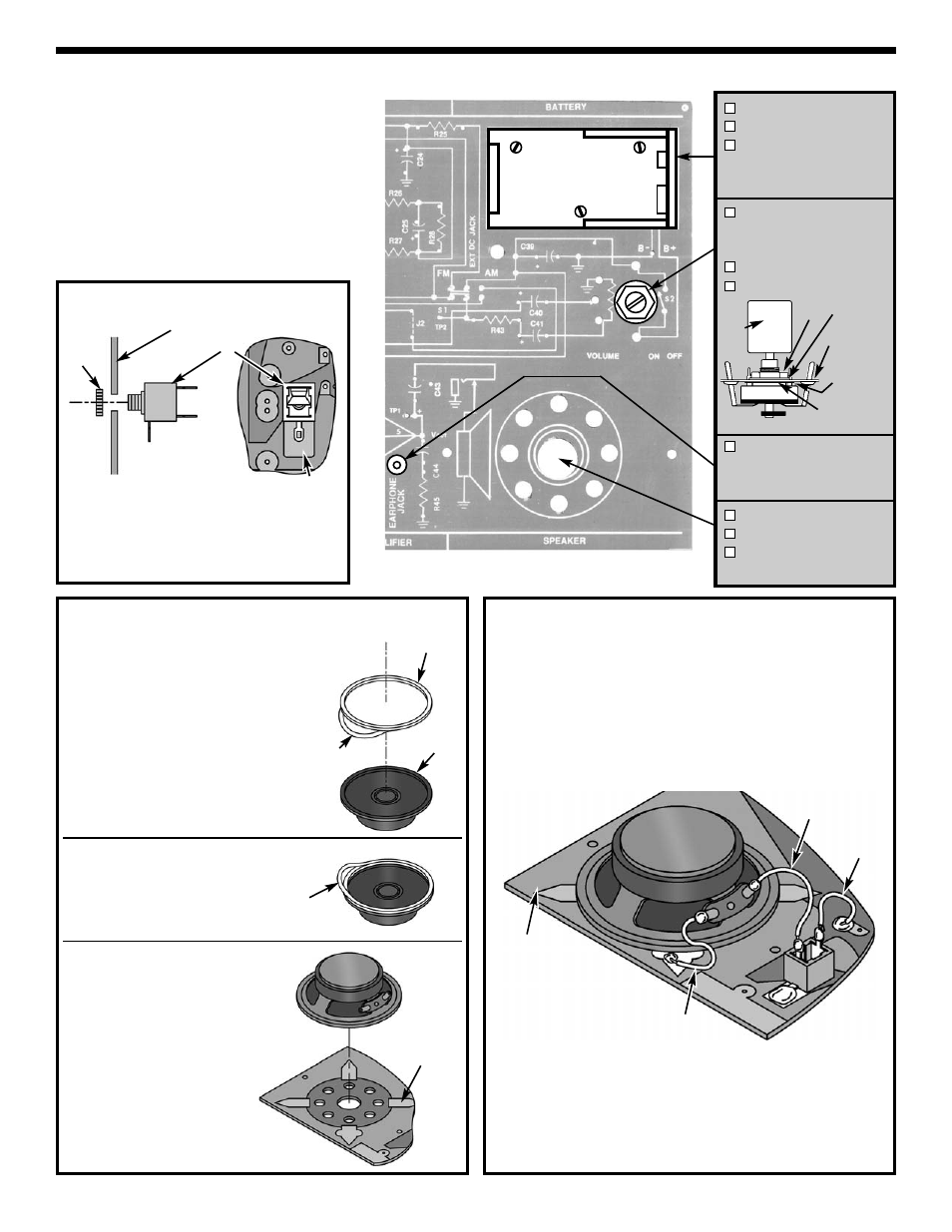
Figure E
Figure F
Step 1:
If the speaker pad has
center and outside pieces, then
remove them. Peel the backing off
of one side of the speaker pad and
stick the pad onto the speaker.
Foil side of
PC Board
(green side)
Mount the jack with the nut from the foil (green)
side of the PC board (terminal #1 on the GND pad
of the PC board). Be sure to line up the tab with the
pad on the foil side of the PC board. Solder
terminal #1 to the pad of the PC board.
1 - GND
2 - Tip
3 - N.C. Tip
Foil (green) side
1
3
2
GND pad
Jack
Nut
Knob
Nut
Washer
Cut off
locating pin
Plastic washer
** Solder all 5 tabs to PC board **
Legend
(blue) side
of PC board
Cut two 1” wires and one 1½” wire and strip ¼” of
insulation off of both ends. Solder the wires in the
locations shown.
Figure G
1” Wire
1½” Wire
1” Wire
Foil side of
PC Board
(green side)
Backing
Pad
Backing
Speaker
Step 3: Stick the speaker onto
the solder side of the PC board.
Step 2: Remove the other backing
from the speaker pad.