Elenco AM/FM Radio Kit User Manual
Page 38
-37-
Set the RF generator at 455kHz, modulation of
400Hz 80% and minimum voltage out. Set the
oscilloscope to read 0.1 volts per division and turn
the power ON. Increase the amplitude of the
generator until the oscilloscope shows a 400Hz
sinewave 5 divisions or 0.5 volts pp. With an
alignment tool or screwdriver adjust T6 for a peak.
Reduce the generator amplitude so that 5 divisions
are maintained. Adjust T7 for a peak and reduce that
amplitude again if necessary. Repeat these steps to
optimize the IF alignment. This process aligns the IF
amplifiers to 455kHz.
After the IF alignment is complete, lower the
frequency of the generator until the voltage drops
0.707 of its peaked value or 0.35Vpp. Record the
frequency of the lower 3dB corner here:
Fl = _________kHz.
Increase the frequency of the generator past the
peak until the voltage seen on the scope drops 0.707
of its peaked value or 0.35Vpp. Record the frequency
of the high 3dB corner here:
Fh = __________kHz.
The bandwidth of the IF is equal to BW = Fh - Fl. The
IF’s bandwidth should be around 6kHz. Turn the
power OFF and remove the short from the
collector of Q7 to TP6.
Calculate the bandwidth: __________kHz.
OSCILLATOR ALIGNMENT
Set the RF generator at 540kHz, 400Hz 80% AM
modulation and a low level of output. Turn the power
ON and set the volume control to a comfortable level.
Turn the tuning knob counter-clockwise until the
white pointer is aligned at the 540kHz marking on the
dial. With an alignment tool or screwdriver adjust L5
until a 400Hz tone is heard. Adjust L5 for a peak on
the oscilloscope. Adjust the amplitude of the RF
generator to maintain a level of 0.5 volts peak to peak
or less. After peaking L5, set the generator frequency
to 1600kHz. Turn the tuning knob clockwise until the
white pointer is aligned to the 1600kHz marking on
the dial. With an alignment tool or screwdriver, adjust
the AM oscillator trimmer on the back of the tuning
gang until a 400Hz tone is heard. Adjust the trimmer
for a peak on the oscilloscope. Refer to Figure N for
the location of the AM oscillator trimmer. Repeat
these steps to optimize the oscillator alignment. This
process sets the oscillator range at 955kHz to
2055kHz.
ANTENNA ALIGNMENT
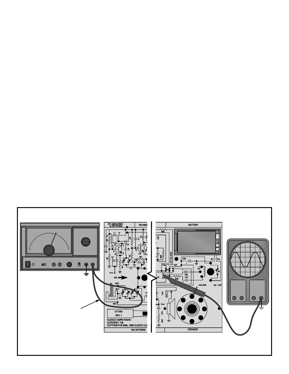
With the power turned OFF, connect your test
equipment as shown in Figure 35.
Figure 35
Battery
GND
TP15
Oscilloscope
GND
TP15
Generator
Wire loop
close to
antenna