Assembly instructions static measurements – Elenco AM/FM Radio Kit User Manual
Page 28
-27-
ASSEMBLY INSTRUCTIONS
STATIC MEASUREMENTS
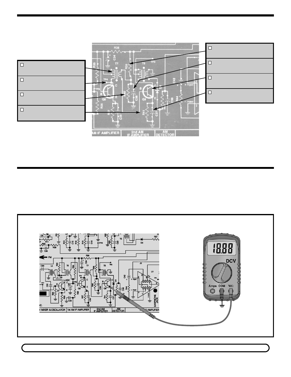
Q9 BIAS
Figure 27
T7 - AM IF Coil
(White Dot)
TP4 - Test Point Pin
(see Figure A)
R40 - 10k
Ω
Resistor
(brown-black-orange-gold)
R41 - 470
Ω
Resistor
(yellow-violet-brown-gold)
R39 - 39k
Ω
Resistor
(orange-white-orange-gold)
C36 - .02
μ
F Discap (203)
or .022
μ
F Discap (223)
Q9 - 2N3904 transistor
(see Figure J)
C37 - .02
μ
F Discap (203)
or .022
μ
F Discap (223)
Connect your VOM as shown in Figure 27. Set the
VOM to read 9 volts DC and turn the power ON. The
voltage at the emitter of Q9 should be approximately
1 volt. If your reading is different by more than 0.5
volts, turn the power OFF and check components
R39, R40, R41 and Q9.
If you do not have an RF generator and oscilloscope, skip to Section 4.
GND
TP15
See also other documents in the category Elenco Toys:
- Upgrade Kit SC100 to SC300 (76 pages)
- Snap Circuits Jr.® Educational 100 Exp. (48 pages)
- Upgrade Kit SC300 to SC500 (64 pages)
- Snap Rover ® (24 pages)
- XP&trade (64 pages)
- Snap Circuits LIGHT ® (84 pages)
- Snap Circuits Extreme® Educational 750 Exp. (88 pages)
- Projects PC1-PC73 (60 pages)
- Electronics 202 (132 pages)
- Snaptricity® (92 pages)
- Upgrade Kit SCROV10 to SCROV50 (48 pages)
- Snap Circuits Green ® (80 pages)
- C Adapter for Snap Circuits® (2 pages)
- Motion Detector Kit (20 pages)
- Digital Roulette Kit (16 pages)
- FM Wireless Microphone Kit (12 pages)
- AM Radio Kit (32 pages)
- AM Radio Kit (36 pages)
- Circuit Maker Skill Builder 125 (64 pages)
- Circuit Maker Sound Plus 200 (80 pages)
- Understanding Logic Gates (16 pages)
- Understanding Logic Gates and Circuits (42 pages)
- Tumbling Robot (12 pages)
- Solar Energy (16 pages)
- C2D Scope (16 pages)
- 288x Astrolon Telescope with Aluminum Tripod (1 page)
- Simulated Frog Dissection Kit (1 page)
- Talking Galaxy Planetarium with Night Light (1 page)
- Night’n Day® (10 pages)
- Radio Controlled Black Widow (1 page)
- Handheld Microscope (2 pages)
- Water Filtration Kit (8 pages)
- 6-in-1 Solar Kit (18 pages)
- Microscope Set in Carrying Case (1 page)
- Mobile 20 Telescope (1 page)
- Mechanical Drum (20 pages)
- Aerial Screw (20 pages)
- Swing Bridge (20 pages)
- Printing Press (24 pages)
- MultiBarrel Cannon (20 pages)
- Armored Car (24 pages)
- Paddleboat (20 pages)
- SelfPropelled Cart (20 pages)
- Catapult (24 pages)