Dynamic measurements – Elenco AM/FM Radio Kit User Manual
Page 19
-18-
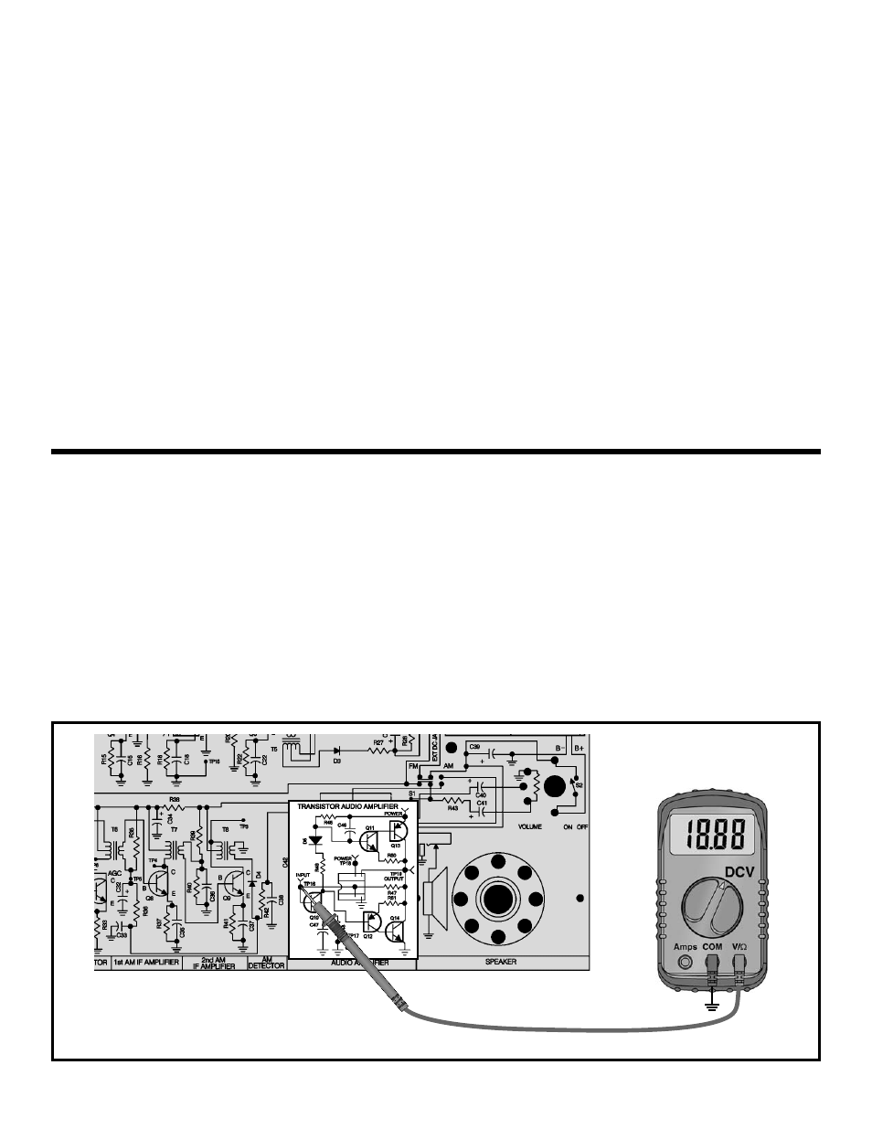
Figure 15
TRANSISTOR BIAS TEST
Adjust your VOM to read 9 volts and connect it as
shown in Figure 14. Make sure that the battery, or a 9
volt power supply (if available), is properly connected
and turn the power ON. The voltage at TP19 should be
between 3 to 6 volts. If you get this reading, go on to the
next test. If your circuit fails this test, turn the power
OFF and check that all of the transistors are correctly
inserted in the correct locations. The E on the transistor
indicates the emitter lead and should always be in the
hole with the E next to it. Check that all resistor values
are the correct value and not interchanged.
DYNAMIC MEASUREMENTS
DC GAIN
The DC gain of the audio amplifier is set by the current
in transistor Q10. Looking at the circuit and assuming
the output bias is 1/2 of V+ or 4.5 volts, the base of Q11
will be 0.7V higher or 5.2 volts. This is because there is
a negligible voltage drop across R50. This means there
is a 3.8 voltage drop across R46. The current through
R46 can now be calculated as 3.8/R46 or 3.8/3.3k
which equals 1.15 milliamps. Since D5 and R49 are
used for biasing transistors Q11 and Q12, the current
through Q10 can be assumed to be 1.15 milliamps. The
DC gain of Q10 can be calculated as the collector
resistor, R46, divided by the emitter resistor plus the
Effective Emitter Resistance. The effective emitter
resistance is actually the dynamic resistance of silicon
and can be calculated by the approximate equation:
Rj = 26 / I(in milliamps)
therefore, Rj = 26 / 1.15 = 22.6 ohms. Now the DC gain
can be calculated as:
R46 / (R48 + Rj) or 3300 / (47 + 22.6) which equals
47.4.
Move the positive lead of your VOM to the base of Q11.
Make sure that the power is ON. The voltage should be
between 0.5 and 0.8V higher than the voltage at TP19.
All silicon transistors biased for conduction will have
approximately 0.7V from the base to the emitter. Now
move the positive lead of your VOM to the base of Q12.
The voltage at this point should be between 0.5 and
0.8V lower than the voltage at TP19. This is because
Q12 is a PNP type transistor. Turn the power OFF. If
your circuit fails this test, check the Q11 and Q12 are
properly inserted in the circuit board. All static tests
must pass before proceeding to the Dynamic Tests or
the next section.
GND
TP17