Dunkirk Excelsior EXB Series User Manual
Page 46
46
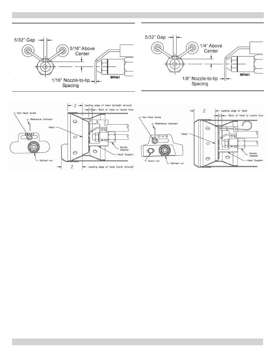
Figure 39 - Beckett Electrode Tip Adjustments
Standard Dimensions (L1, V1) Heads
Figure 40 - Beckett Electrode Tip Adjustments
Standard Dimensions (L2) Heads
17 - OIL BURNER, NOZZLE, & AIR SETTINGS
Figure 41 - Beckett Check/Adjust “Z”
Dimensions L1 & L2 Heads
Figure 42 - Beckett Check/Adjust ‘Z’ Dimension -
V1 Heads
L1/L2 Heads
See Figure 39. The important “Z” dimension is distance
from leading edge of head to end of air tube. This distance
for L1 & L2 heads is 1-3/8” if the tube has a straight shroud
or 1-3/4” if air tube has conic shroud. “Z” dimension is fac-
tory set for burners shipped with air tube installed. Even if
factory set, verify “Z” dimension has not been changed.
1.
Use following procedure to adjust “Z” dimension, if it is
not correct:
• Turn off power to burner.
• Disconnect oil connector tube from nozzle line.
• Refer to figure above. Loosen splined nut from nozzle
line. Loosen hex head screw securing escutcheon
plate to burner housing.
• Place end of ruler at leading edge of head and, using
straight edge across end of airtube, measure distance
to end of tube. A Beckett T501 gauge may also be
used.
• Slide nozzle line forward or back until this dimension
is 1-3/8” for L1 & L2 heads if tube has straight
shroud, or 1-3/4” if air tube has conic shroud.
• Tighten hex head screw to secure escutcheon plate to
burner chassis. Then tighten splined nut and attach
oil connector tube.
2.
Recheck “Z” dimension periodically when servicing to
ensure escutcheon plate has not been moved. Reset
“Z” dimension if you replace air tube or nozzle line
assembly.
V1 heads
See Figure 40. The important “Z” dimension is distance
from leading edge of head to end of air tube. This distance
for V1 heads is 1-¾”. “Z” dimension is factory set for
burners shipped with air tube installed. Even if factory set,
verify “Z” dimension has not been changed.
1.
Use following procedure to adjust “Z” dimension, if it is
not correct:
• Turn off power to burner.
• Disconnect oil connector tube from nozzle line. Refer
to figure above. Loosen splined nut from nozzle line.
Loosen hex head screw securing escutcheon plate to
burner housing.
• Loosen acorn nut. Move head adjusting plate until
“0” lines up with reference indicator on housing, and
tighten hex head screw. Place end of ruler at leading
edge of head and, using straight edge across end of
air tube, measure distance to end of tube. A Beckett
T501 gauge may also be used.
• Slide the nozzle line forward or back until this
dimension is 1-¾” for V1 heads. Tighten acorn nut.
• Tighten hex head screw to secure head adjusting
plate to burner chassis. Then tighten splined nut and
attach oil connector tube.
2.
Recheck “Z” dimension periodically when servicing to
ensure escutcheon plate has not been moved. Reset
“Z” dimension if you replace air tube or nozzle line
assembly.