7 alm input, Alm input, Figure 3-8 – ADLINK AMP-208C User Manual
Page 64: Servo alarm signal connection example
50
Signal Connection
3.7
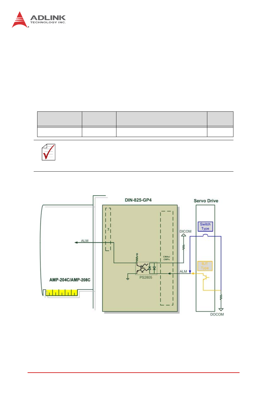
ALM Input
AMP-204C / AMP-208C provides 4/8 servo alarm input channels.
Working with function described in Section 4.11 it can be used as
the trigger source for motion interrupt event. In general, when
abnormality is encountered during servo drive movement, it issues
an (ALM) pulse signal to controller for abnormality occurrence.
See below for corresponding pins of servo alarm input on
DIN-825-GP4:
• Signal connection diagram:
Figure 3-8: Servo alarm signal connection example
CMAx / CMPx
Pin No (x=1~4)
Signal Name
(n=1~4)
Description
Axis #
11
ALM(n)
Servo alarm input
1~4
NOTE
NOTE
AMP-208C requires two DIN-825-GP4 for eight axes motion
control functions
# 1 controls axes 1 ~ 4 and #2 controls axes 5 ~ 8
This manual is related to the following products: