J2: • j3: • j4: brake connector – ADLINK AMP-208C User Manual
Page 45
Getting Start with The Installation
31
AMP-204C / AMP-208C
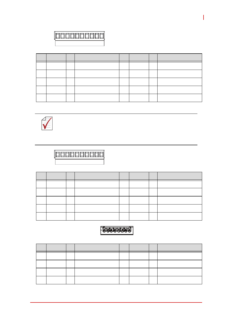
• J2:
• J3:
• J4: Brake Connector
No.
Name
I/O
Function of Axis
No.
Name
I/O
Function of Axis
1
DICOM
--
Digital input common
6
EDI2
|
Isolated digital input, (2)
2
EDI1
|
Isolated digital input, (1)
7
PEL2
|
Positive limit, (2)
3
PEL1
|
Positive limit, (1)
8
ORG2
|
Origin Signal, (2)
4
ORG1
|
Origin Signal, (1)
9
MEL2
|
Negative limit, (2)
5
MEL1
|
Negative limit, (1)
10
DOCOM
--
Digital output common
NOTE
NOTE
1. Please connect DICOM to external power supply
(24VDC in general) if possible.
2. Please connect DOCOM to ground (GND) of
external power supply if possible.
No.
Name
I/O
Function of Axis
No.
Name
I/O
Function of Axis
1
DGND
--
Isolated digital ground
6
AGND
--
Analog ground
2
TRG2-
c
Trigger output (-), (2)
7
AI4
|
Analog input, (4)
3
TRG2+
c
Trigger output (+), (2)
8
AI3
|
Analog input, (3)
4
TRG1-
c
Trigger output (-), (1)
9
AI2
|
Analog input, (2)
5
TG1+
c
Trigger output (+), (1)
10
AI1
|
Analog input, (1)
No.
Name
I/O
Function of Axis
No.
Name
I/O
Function of Axis
1
BRAKE 1+ --
Brake signal (+), (1)
6
BRAKE 3+ |
Brake signal (+), (3)
2
BRAKE 1-
|
Brake signal (-), (1)
7
BRAKE 3-
|
Brake signal (-), (3)
3
BRAKE 2+ |
Brake signal (+), (2)
8
BRAKE 4+ |
Brake signal (+), (4)
4
BRAKE 2-
|
Brake signal (-), (2)
9
BRAKE 4-
|
Brake signal (-), (4)