Verifying load ceil output and input sensitivity, Verifying load cell output and input sensitivity – A&D Weighing Indicator AD-4329 User Manual
Page 8
Attention! The text in this document has been recognized automatically. To view the original document, you can use the "Original mode".
3.1.3. Adjustment of the Load Ceil Output
Caution a Use a inetaf film resistor in the range of 50kQ to 500kQ with a good
temperature coefficient when adding a resistor to adjust a load cell
output. Use as a large resistance value as possible in the range in which
zero adjustment is possible. Solder this resistor at a point near the load
cell or the indicator.
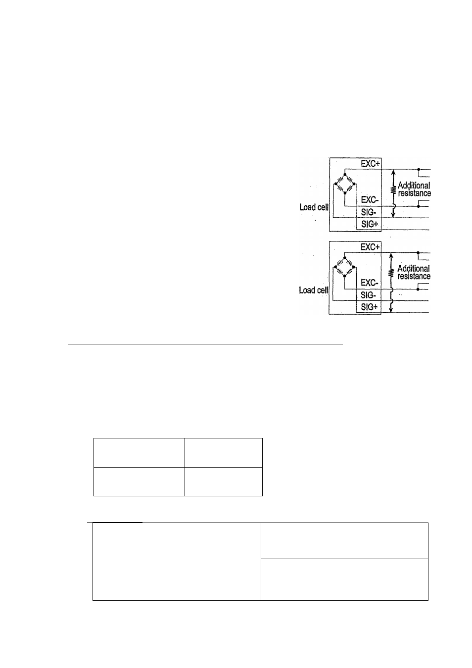
In Case of Reducing the Output Voltage
When the zero output is too large, add a resistor
between EXC+and SIG-.
in Case of Adding an Offset Voltage to the Output
When the zero output is too small, add a resistor
between EXC+ and S1G+.
3.1.4.
Verifying Load Ceil Output and Input Sensitivity
The input sensitivity of the indicator is 0.2pV/division or more. Adapt to the following
inequality, when you design a weighing instrument using the indicator and load cell(s).
Caution □ A change in input voltage sensitivity is equivalent to a one division
change of the display. Select as large an Input voltage sensitivity voltage
as possible so that the weighing interval becomes stable,
a Consider the leverage If a lever is used.
Weighing
instrument
using one load ceil.
E^tB^D
0.2 £------------
A
, Weighing Instrument
using multi-load cell
E^B
h
^D
0.2^——~
A^N
A: Rated capacity of load cell [kg]
B: Rated output [mVA/]
D: Weighing interval [kg]
E: Excitation voltage [mV]
N: Number of load cells
Verification Example
Design;
Load cell
N=1
Rated capacity
A=750 [kg]
6000*3*0.05 , ^
„ -j ^ 0.2. Therefore,
Rated output
8=3 [mVA/I
750
Excitation voltage
E=5000 [mV]
regard the instrument as a good design.
Weighing interval
D=0.05 [kg]
Weighing capacity
300 [kg]
3. Insteilatìon and Precaution
Page 6
AD-4329 Weighing Indicator