Installation and precautions, Зл .1. instailation and precautions, The load cell connections – A&D Weighing Indicator AD-4329 User Manual
Page 7: The load ceil connections, Cable, Cable exc+ exc- sig- s1g+ load ceii
Attention! The text in this document has been recognized automatically. To view the original document, you can use the "Original mode".
3. Installation and Precautions
ЗЛ .1. Instailation and Precautions
Aa
A
d
□
The AD-4329 weighing indicator is a precision electronic instrument Handle the
Indicator carefully.
The operating temperature is -10t: to *f40t: (14“F to 104"^).
Do not install the scale in direct sunlight.
Misoperation or other problems may be caused by an unstable power source including
momentary power failrue or instantaneous noise. Use a stable power source.
Do not connect the power cord before the installation Is finished.
Please confirm that the local voltage and receptacle type are correct for your scale.
The jOperate/Standbvi key @ key) can not cut the power. The load cell and the internal
circuit are supplied with power in the standby state.
Use shielded cable for ail connections. Connect the cable shields to the shield
terminal or case as an earth terminal.
Earth ground the indicator. Do not Join the earth ground line with other electric power
equipment. There is an earth ground terminal at the power cord receptacle.
Do not install the scale in a place where it is af3t to be charged with static electricity,
or where the relative humidity is lower than 45%RH. Plastic and isolators are apt to be
charged with static electricity.
3.1.2.
The Load Cell Connections
□
□
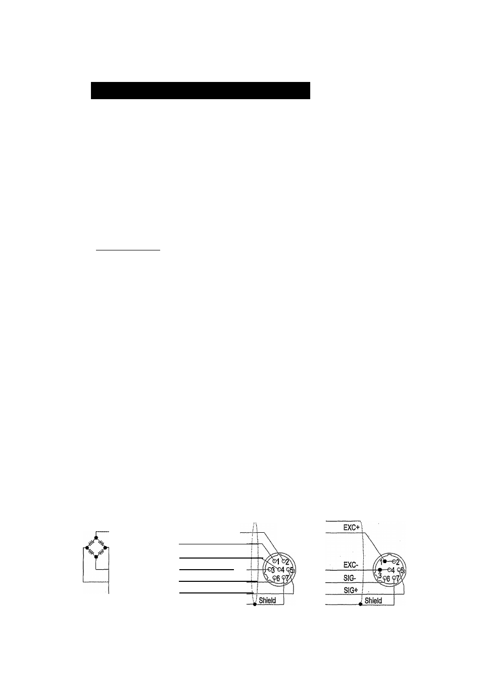
Connect the load ceil wires to the connector (receptacle), at the rear panel, using the
accessory load cell plug.
It is possible to connect a 4 wire cable that 1 pin"2pin and 3pin-4pin are shorted, if the
distance between the indicator and a load cell is shorter than 5m.
The output voltage of a load ceil is a very sensitive signal. Space the load cell cable
away from any noise source.
It is possible to connect eight 350Q load cells.
The load cel! drive is 5VDC ± 5% between EXC+ and EXC-, the maximum current 120mA.
Cable
Cable
EXC+
EXC-
SIG-
S1G+
Load ceii
i\
Positive Sense
Positive Excitation Input
Negative Excitation input
Negative Sense
Negative signal Output
Positive signai Outpur
Load Cell Plug
Standard
connection
AD-4329 Weighing Indicator
Page 5
Available connection for
a cable shorter than 5m.
3. Installation and Precaution