Check or test, If ^ /^ Page 64
Page 64
Attention! The text in this document has been recognized automatically. To view the original document, you can use the "Original mode".
CHECK OR TEST
(C heck or test in sequence show n
until problem is resolved.)
-
^
///“^
Throttle lever in “S TA R T” position
X
14
W heels/Tines/P TO D rive Lever in
“N EU TR A L” position
X
9
Forw ard Interlock W ire H arness
connector securely m ated
X
X
61
Forw ard Interlock Levers not being
squeezed prior to shifting W heels/
Tines/P TO D rive Lever to
“FO R W A R D ” position
X
10
V isually inspect for bare, broken
or disconnected w ires
X
X
61
C heck handlebar w ire harness
X
X
62
C heck transm ission w ire harness
X
X
63
c*
if ^ /^
■p ff* >
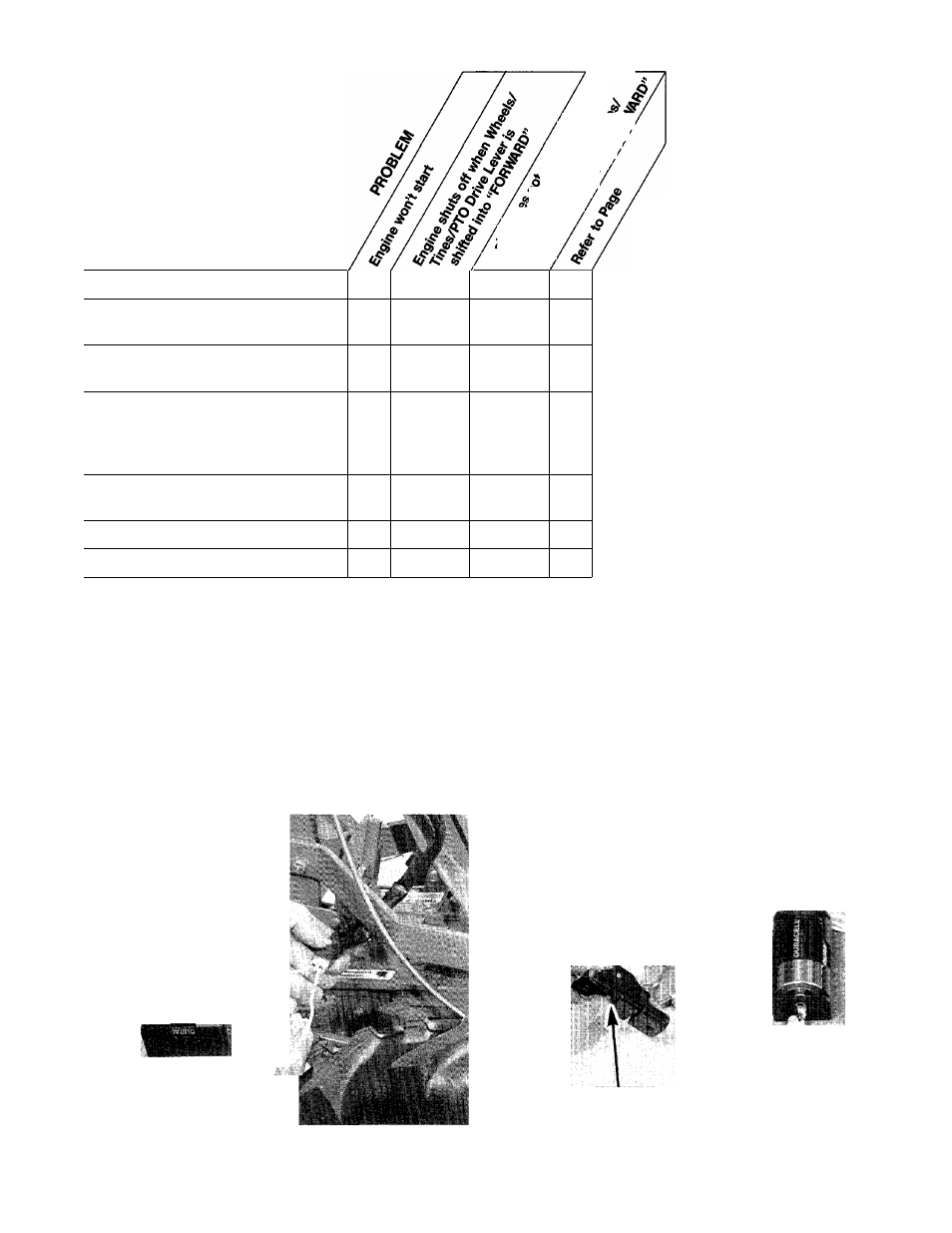
Checking the Handlebar Wiring
Harness
The purpose of this test is to see
that there is a continuous circuit
betw een the term inals on the han
dlebar w iring harness interlock
plug and the sw itches and w ires
inside the handlebars.
1. To perform this test you w ill
need a continuity m eter (volt-ohm
m ultitester) or a sim ple battery-
pow ered continuity tester, such as
the one show n on page 59 of this
M anual.
2. A fter unplugging the w iring har
ness connector, place the leads
from your tester into the tw o term i
nal holes in the interlock plug (see
P hoto 6-77). The tester bulb should
glow . N ow m om entarily squeeze
«iv..
r->
6-77: Test continuity between terminals.
each of the Forw ard Interlock
Levers, one at a tim e. The bulb
should go out as either lever is
squeezed.
If the bulb did not glow during
this test, it indicates a possible
broken w ire, or a w ire that has
pulled loose from one of the
sw itches in the handlebars.
3. R em ove one sw itch at a tim e
(see “S w itch R em oval” instructions
further on), and check the tw o
w ires on each sw itch for a tight
connection. (The w ires m ay be
attached to either term inal on the
sw itch. H ow ever, the longer (red)
w ire should be attached to the top
of the sw itch.) A fter checking the
connections, check for continuity
betw een the tw o term inal holes In
the interlock plug as described in
S tep 2 above. W hen m aking this
test, the tiny sw itch plunger (show n
in Photo 6-78) on both sw itches
m ust be depressed either w ith your
finger or by the interlock lever.
4.
If the bulb still doesn’t glow , you
should rem ove the w ires from the
sw itch. Then touch the leads from
your tester to the tw o term inals on
the sw itch and press the tiny
sw itch plunger (see P hoto 6-78).
4
y-r
PLUNGER
6-78: Test switch terminals while depressing switch plunger.
62