Handlebar height adjustment lever, To operate the height adjustment lever, A warning – Troy-Bilt 8 HP User Manual
Page 15: Engine controls, Engine throttle lever, Important, To operate the engine throttle lever, Engine, Fümctioms
Attention! The text in this document has been recognized automatically. To view the original document, you can use the "Original mode".
FüMCTiOMS
6. Handlebar Height
Adjustment Lever
This lever is located near the
bottom of the handlebars, on the
right side of the tiller. See Photo
2-8. It allows you to adjust the han
dlebars up or down to any of four
different settings.
As a general rule, the handlebars
should be adjusted to approxi
mately waist level when the tines
are 3 to 4-inches in the soil, but
you should try different settings to
find the one that is most comforta
ble for you.
» s
N
1
2-8: Handlebar Height Adjustment
Lever.
To operate the Height Adjustment
Lever:
A. Stop the engine before adjust
ing the handlebars.
B. Support the handlebars with
one hand while unwinding the lever
enough so that the teeth in the
ratchets are disengaged.
C. Move the handlebars up or
down to either of two preset height
adjustment settings and then re
tighten the lever securely.
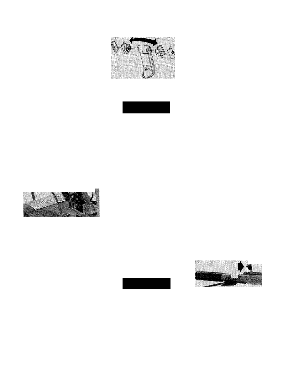
D. Two additional height settings
can be obtained by switching the
inside handlebar ratchets, as
shown in Figure 2-9. This will
change the handlebar height a few
inches higher or lower than the
lowest setting obtained in Step C.
2-9: Switch ratchets to obtain two
more height settings.
A
WARNING
For use with the PTO Chipper/
Shredder Attachment only, the
handlebars can be swung 30° to
the right side by loosening the
mounting bolt at the bottom of the
handlebar base. NEVER OPERATE
THE TILLER OR OTHER ATTACH
MENTS WITH THE HANDLEBARS
SWUNG OUT TO THE RIGHT SIDE.
Doing so could result in unsafe
handling and personal injury.
ENGINE
CONTROLS
The following are descriptions of
the controls on your 7 HP Briggs &
Stratton Engine or
8
HP Kohler
Engine. Additional information on
the safe, efficient operation of your
engine is given in the engine man
ufacturer’s Owner’s Manual which
was included in your literature
package. Please read that literature
carefully and save it for future
reference.
A
WARNING
To avoid personal injury or dam
age to equipment, do not attempt
to start your engine at this time.
Complete starting instructions for
the engine are given in Section 3,
“Operation of Tiller.”
1. Engine Throttle Lever
This lever is located on the right
side handlebar (see Photo 2-10). It
is used to regulate engine speeds
as well as to start and stop the
engine.
In general, faster engine speeds
will be required when breaking new
ground or tilling under heavy crop
residues, but remember to use
only as fast an engine speed as is
needed to do the job. Try to judge
when the engine is providing the
proper amount of power—not too
little, but not too much. The sound
of the engine running will be your
best guide.
IMPORTANT
Factory settings of the throttle cable
should be satisfactory for most con
ditions. If adjustments are needed,
refer to Section
6
of this Manual.
To operate the Engine Throttle
Lever:
A. When starting the engine, first
make certain that the Wheels/
Tines/PTO Drive Lever is in “NEU
TRAL”. Then, place the lever ap
proximately halfway between the
“SLOW” and “FAST” throttle set
tings. This position should provide
the carburetor with sufficient gas
oline flow to start the engine. How
ever, you may need to experiment
the first few times to find that “just
right” starting position.
B. For faster engine speeds move
the lever forward toward the
“FAST” setting; for slower speeds
.......
2-10: The Engine Throttle Lever.
move it backward toward the
“SLOW” setting.
C. To stop the engine, move the
lever all the way back to the
“STOP” position (during normal
operation you would first place the
Wheels/Tines/PTO Drive Lever in
“NEUTRAL” and then release both
Forward Interlock Levers before
stopping the engine).
13