How to adjust belt tension – Troy-Bilt 8 HP User Manual
Page 44
Attention! The text in this document has been recognized automatically. To view the original document, you can use the "Original mode".
3. The belt tension is correct if the
front of the clutch roller is 1/4 to
5/16-inches away from the face of
the upright bracket that holds the
adjustment block in place (Photo
6-14). To measure this distance:
(a) Without moving the clutch
roller, try to insert the V4-inch
thick, slotted end of the belt
adjustment tool in between the
roller and the bracket. The flat
edge of the tool must be facing
the roller. See Photo 6-15.
(b) If only the slotted end of the
tool will fit, the belt is properly
adjusted. This V4-inch gap is
ideal.
(c) If the slotted end will not fit, the
belt is too loose.
(d) If the full thickness (5/16-inch)
of the tool easily fits, the belt is
too tight.
4. If the belt tension is correct,
return the shift lever to the “NEU
TRAL” position and check the ten
sion again after the next 10 operat
ing hours. If the belt is too loose or
too tight, refer to the adjustment
instructions that follow.
How to adjust belt tension:
1. The tension on the drive belt is
adjusted by moving the belt adjust
ment block either down to tighten
the belt, or up to loosen the belt.
As a rule of thumb, the distance
the block moves will approximately
equal the distance the roller
moves. In most cases, the clutch
roller will not have been very far
out of position, and therefore only
a slight movement of the block will
be required.
2. Place the Wheels/Tines/PTO
Drive Lever in “NEUTRAL”. The
clutch roller will come to rest any
where on the face of the belt ad
justment block, depending upon
drive belt length and future adjust
ments for belt tension.
3. Insert the belt adjustment tool
through the hole in the side of the
adjustment block, spacing the
ends of the tool equally on both
sides (Photo 6-16). Rotate the tool
so that the slotted end is fac
ing down.
6-15: Insert slotted end of belt adjust
ment tool between roller and bracket,
with flat side of slot facing roller.
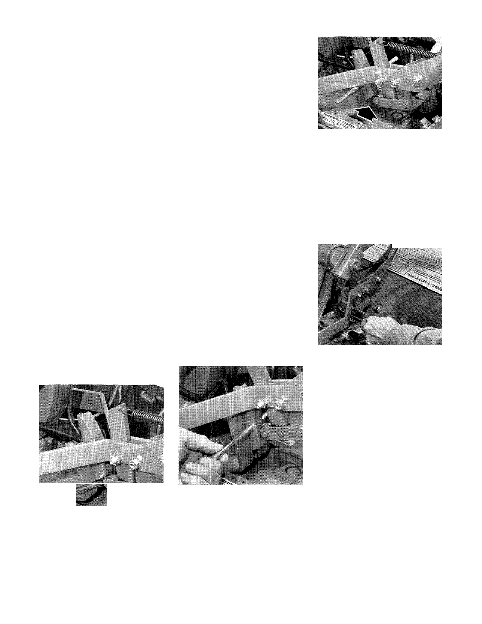
6-16: With shift lever in “NEUTRAL”,
insert tool through hole in adjustment
block.
4. Place the Wheels/Tines/PTO
Drive Lever in “FORWARD”. The
arms of the clutch control yoke will
be resting on the belt adjustment
tool and the clutch roller should be
engaged slightly beneath the ad
justment block (Photo 6-17).
6-17: With shift lever in “FORWARD”,
clutch roller should be engaged
slightly beneath adjustment block.
5. Use one hand to hold the drive
lever in “FORWARD” while using a
9/16-inch wrench to loosen (do
not remove) the bolt in the back of
the belt adjustment block (Photo
6-18).
6-18: Hold lever while loosening bolt.
Push lever down to tighten belt or pull
up to loosen belt.
6. Push the drive lever down if the
belt needs tightening, or pull the
lever up if the belt needs loosen
ing. The adjustment block should
move freely in either direction. Hold
the drive lever in place and se
curely tighten the bolt in the adjust
ment block.
7. Let go of the drive lever and
remove the belt adjustment tool
from the hole in the adjustment
block.
8. Check the tension on the belt
by following the previous “How to
Measure Belt Tension” instructions.
NOTE: If the adjustment block has
moved all the way down in its
bracket and you still measure less
than ’/4-inch between the clutch
roller and the bracket, then the
belt has worn too much and a new
one is needed.
42