Tighten bolts and nuts, A warning, Important – Troy-Bilt 8 HP User Manual
Page 39
Attention! The text in this document has been recognized automatically. To view the original document, you can use the "Original mode".
Tighten bolts and nuts
MAIMTEMAMCE AND SERVICE
A
WARNING
To help avoid personal injury, stop
the engine, remove the eiectric start
key, disconnect the spark plug wire,
and iet the engine and muffler coo!
before inspecting or servicing the
tilier or engine.
It’s a good idea to check for
loose or missing bolts, nuts and
screws after every 10 operating
hours. Failure to tighten or replace
fasteners can result in poor per
formance, equipment damage, or
oil leaks. If you need to replace a
fastener, be sure to refer to your
Parts Catalog for the correct size
and for any special grade specifi
cation. Most fasteners are available
locally, or you can order directly
from our Parts Department.
Most bolts, nuts and screws on
your tiller are easily visible. Please
refer to Photos 6-1, 6-1A and 6-2
for the following fasteners that re
quire special attention.
1. Check transmission pulley
mounting bolt (Photo 6-1). If
washer behind bolt head is loose.
1
then bolt must be tightened se
curely. To tighten bolt, insert a
punch or thick screwdriver into the
hole next to the bolt and wedge
the tool against the side of the
motor mount casting. This will pre
vent the pulley from turning as you
tighten the bolt.
2. Check jam nut on left side of
neutral plunger assembly (Photo
6-1 A). If loose, place one wrench
on head of bolt and tighten jam nut
with second wrench.
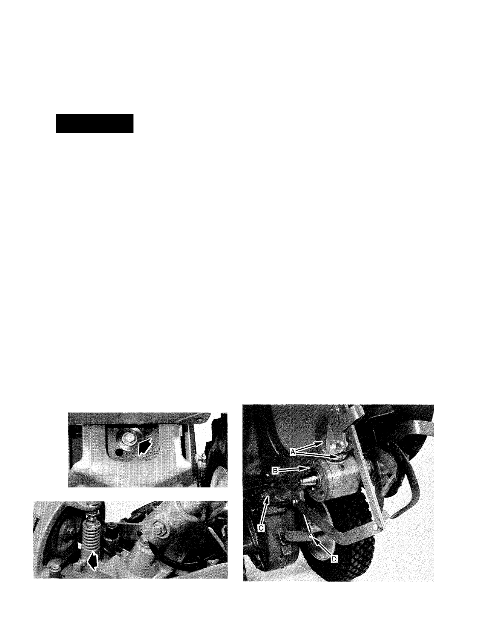
3. Check the three rear bearing
cap screws that are located under
neath the depth regulator mount
ing bracket assembly (“A” in Photo
6-2). If these screws are loose it
could cause an oil leak or exces
sive end play in the drive shaft.
At.
Check the five bolts that fasten
the tiller housing cover to the left
side of the transmission (“B” in
Photo 6-2). If the bolts or cover are
loose, it could cause an oil leak. To
gain access to the housing cover,
you will have to remove the left
side tine holder. See “Bolo Tine
Maintenance” in this Section for
tine holder removal instructions.
5. Check the two swing-bolts that
connect the power unit transmis
sion to the tine attachment (“C” in
Photo 6-2). These bolts should be
checked after every
2
-V
2
hours of
operation. Failure to do so could
cause excessive wear to the locat
ing pin on the power unit, and
enlargement of the locating hole in
the tine attachment. The bolts must
be kept very tight. If you have a
torque wrench, tighten each to 70-
80 ft. lbs.
6. Check the locknut that fastens
the shifting linkage to the eccen
tric shifting lever (“D” in Photo
6-2). Do not tighten the locknut
against the eccentric lever. It
should be very close to, but not
touching the lever.
IMPORTANT
Screws or bolts that thread into
the transmission housing should
be coated w-th a non-hardening
gasket sealant (available at hard
ware or automotive supply storosi.
The sealant helps to prevent oil
from leaking past the threads.
6-1: Check bolt on transmission pulley.
6-1 A: Check jam nut on plunger assembly.
6-2: Gently tilt tiller forward to check these fasteners.
37