Inspect forward interlock wiring system, Aistekamce, Serwicl – Troy-Bilt 8 HP User Manual
Page 63
Attention! The text in this document has been recognized automatically. To view the original document, you can use the "Original mode".
Inspect Forward Interlock Wiring System
■ AiSTEKAMCE
mQ
SERWiCl
E very 10 operating hours you
should check the Forw ard Interlock
w iring system to m ake sure that all
connections are tight, and that a
break in the insulation is not allow
ing a bare w ire to touch any m etal
surfaces.
1. C heck the insulated w ire har
ness that leads from the low er ends
of the handlebars over to the w ire
harness connector on the top,
right side of the transm ission cover
(see Photo 6-76). N ext check that
the connector is securely m ated.
2. C heck the insulated tubing that
leads from the connector over to
the cast iron m otor m ount/belt
shroud. C heck the w ire that leads
from the tubing over to the sw itch
assem bly m ounted on top of the
tab on the cast iron m otor m ount/
belt shroud (see P hoto 6-74). Then
check the second w ire that leads
to the throttle cable m ounting
bracket on the right side, for
w ard portion of the engine.
TW>ubleshooting the Forward Interlock Safety System
The w iring circuit for the Forw ard
Interlock S afety S ystem is de
signed to ground out the engine’s
ignition system , m uch like a spark
plug shutoff clip found on m any
sm all engines.
There are three sw itches in the
circuit w hich, w hen open, allow the
engine to run. O ne sw itch is lo
cated on the neutral plunger tab of
the cast iron m otor m ount (see
P hoto 6-74). This sw itch is opened
w henever the W heels/Tines/P TO
D rive Lever is in the “N EU TR A L”
or “R EV E R S E ” positions.
The other tw o sw itches are
located inside the handlebars, di
rectly above the tw o Forw ard Inter
lock Levers (see Photo 6-75). The
sw itches are w ired in series so
that w hen either one is opened (by
squeezing one of the Forw ard Inter
lock Levers), the engine w ill run.
There is a fourth sw itch that is
located in the w iring harness con
nector on the top, right side of the
transm ission cover (see P hoto
6-76). This sw itch w arns you if
the connection is not m ated by not
allow ing the engine to run w hile
the W heels/Tines/P TO D rive Lever
is in “FO R W A R D ”.
There are only a few things that
could go w rong w ith a sim ple cir
cuit such as this:
1. A broken or disconnected w ire
could create an open circuit and
allow the engine to run w ithout
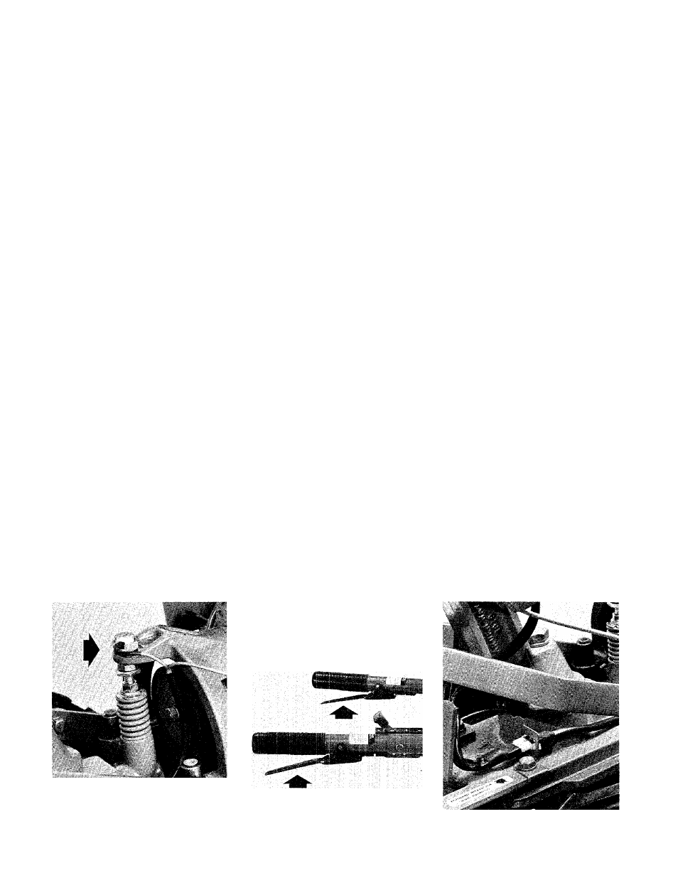
6-74: Neutral plunger switch.
6-75: Forward interlock Levers.
61
your having to squeeze one of the
Forw ard Interlock Levers.
2.
A bare w ire that touches any
part of the tiller or engine could
ground out the engine’s ignition,
regardless of the position of the
sw itches. This, of course, w ould
prevent the engine from running.
3. A sw itch that has failed inter
nally or that is not being actuated
m echanically m ay act as an open
sw itch and allow the engine to run.
O r, it m ay act as a ground and
prevent the engine from running.
P lease refer to the troubleshoot
ing chart on page 62 if your sys
tem is not operating correctly.
6-76: Wiring harness connector.