Throttle cable adjustments, A warning, B. to adjust the 8 hp kohler throttle cable – Troy-Bilt 8 HP User Manual
Page 55: Warning, High speed g stop screw, shutoff-"-— switch, S, f, Controll ^ arm, Clamp' i .'screw
Attention! The text in this document has been recognized automatically. To view the original document, you can use the "Original mode".
Throttle cable
adjustments
The throttle lever settings have
been factory adjusted and unnec
essary adjustm ents should not be
m ade. H ow ever, if the engine does
not start or stop, or if it does
not respond im m ediately to vari
ous throttie lever settings, then
the follow ing adjustm ents m ay
be necessary.
A
WARNING
To help avoid personal injury, stop
the engine, rem ove the electric
start key, disconnect the spark
plug w ire, and let the engine and
m uffler cool before adjusting the
throttle cable.
A. To adjust the 7 HP
Briggs & Stratton
throttle cable
1. M ove the throttle lever on the
handlebar to the “FA S T” position.
2. W ith the lever In the “FA S T”
position, the S peed C ontrol Lever
(see Photo 6-56) on the throttle
control bracket should be located
all the w ay forw ard in its m ounting
slot (see Fast S peed setting in
P hoto 6-56). If it is, go on to S tep
4. If it isn’t, proceed to Step 3.
3. Loosen (do not rem ove) the
C able C lam p Screw (see P hoto
6-56) until the throttle cable is free
to m ove. Then m ove the cable for
w ard until the S peed C ontrol Lever
reaches the end of the slot. Tighten
the C able C lam p S crew securely
and proceed to S tep 4.
4. M ove the throttle lever on the
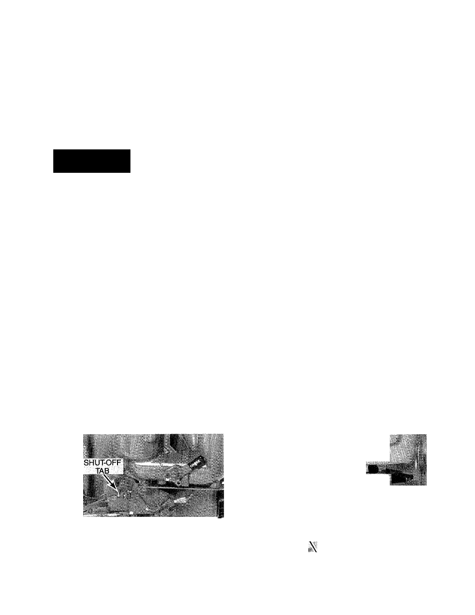
handlebar to the “S TO P ” position.
W hile doing so, look at the S peed
C ontrol Lever and Shut-O ff Tab on
your engine (see P hoto 6-56). A s
the S peed C ontrol Lever reaches
the end of its m ounting slot, the
S hut-O ff Tab should spring out
w ard, aw ay from the engine. If it
does, the throttle cable is properly
adjusted to stop the engine and
further adjustm ents are not neces
sary. If it doesn’t, proceed to
S tep 5.
5. M ove the throttle lever on the
handlebar to the “S TO P ” position
and then loosen (do not rem ove)
the C able C lam p S crew until the
throttle cable is free to m ove. Then
pull the cable back until the Shut-
O ff Tab springs outw ard. Tighten
the C able C lam p S crew securely.
6. Test the operation of the throttle
lever by m oving it back and forth
betw een the “FA S T” and “S TO P ”
positions. A s you do, check that
the S peed C ontrol Lever on the
throttle control bracket functions
as described in S teps 2 and 4. If
you are unable to properly adjust
the cable, call or w rite us for fur
ther advice.
B. To adjust the 8 HP Kohler
throttle cable
1. M ove the throttle lever on the
handlebar to the “S TO P ” position.
mo
service
2. Loosen the C able C lam p S crew
(P hoto 6-57) until the throttle cable
is free to m ove.
3. M ove the C arburetor C ontrol A rm
(P hoto 6-57) to the right until it
touches the E ngine S hutoff S w itch.
R em ove any slack in the throttle
cable and retighten the C able
C lam p S crew .
4. M ove the throttle lever on the
handlebar to the “FA S T” position.
5. C heck that the C arburetor C on
trol A rm (P hoto 6-57) is now touch
ing the H igh Speed S top S crew . If
it isn’t, loosen the C able C lam p
S crew and m ove the C arburetor
C ontrol A rm back until it does.
Then securely tighten the C able
C lam p S crew .
6. C heck the operation of the
throttle control lever as follow s:
(a) M ove the throttle control lever
on the handlebar to the “S TO P ”
position. The C arburetor C on
trol A rm should be touching
the S hutoff Sw itch.
(b) M ove the throttle control lever
to the “FA S T” position. The
C arburetor C ontrol A rm should
be touching the H igh S peed
S top S crew .
(c) If the C arburetor C ontrol A rm
does not touch both the S hut
off Sw itch and the H igh S peed
S top S crew , readjust the cable
settings as explained previ
ously. If you are unable to
properly adjust the cable, call
or w rite us for further advice.
Ï
■ i-
i
C A B LE
C LA M P ■
S C R E W
HIGH SPEED g
STOP SCREW,
SHUTOFF-"-—
SWITCH
A. ‘ -V FAST SPEED
T
' Vi.i SETTING
SPEED ^
s, F"
9- ^ \
^
\ ^
- CONtROLl
^ ARM
CONTROL LEVER'
6-56: Throttle control bracket on 7 HP Briggs & Stratton
Engine.
CLAMP'
i
.'SCREW.,.
6-57: Throttle control bracket on 8 HP Kohler Engine.
53