C. checking and adjusting reverse drive, To replace the reverse disc – Troy-Bilt 8 HP User Manual
Page 47
Attention! The text in this document has been recognized automatically. To view the original document, you can use the "Original mode".
iAlCE
mo
SERVICE
/
■r
C. Checking and adjusting
reverse drive
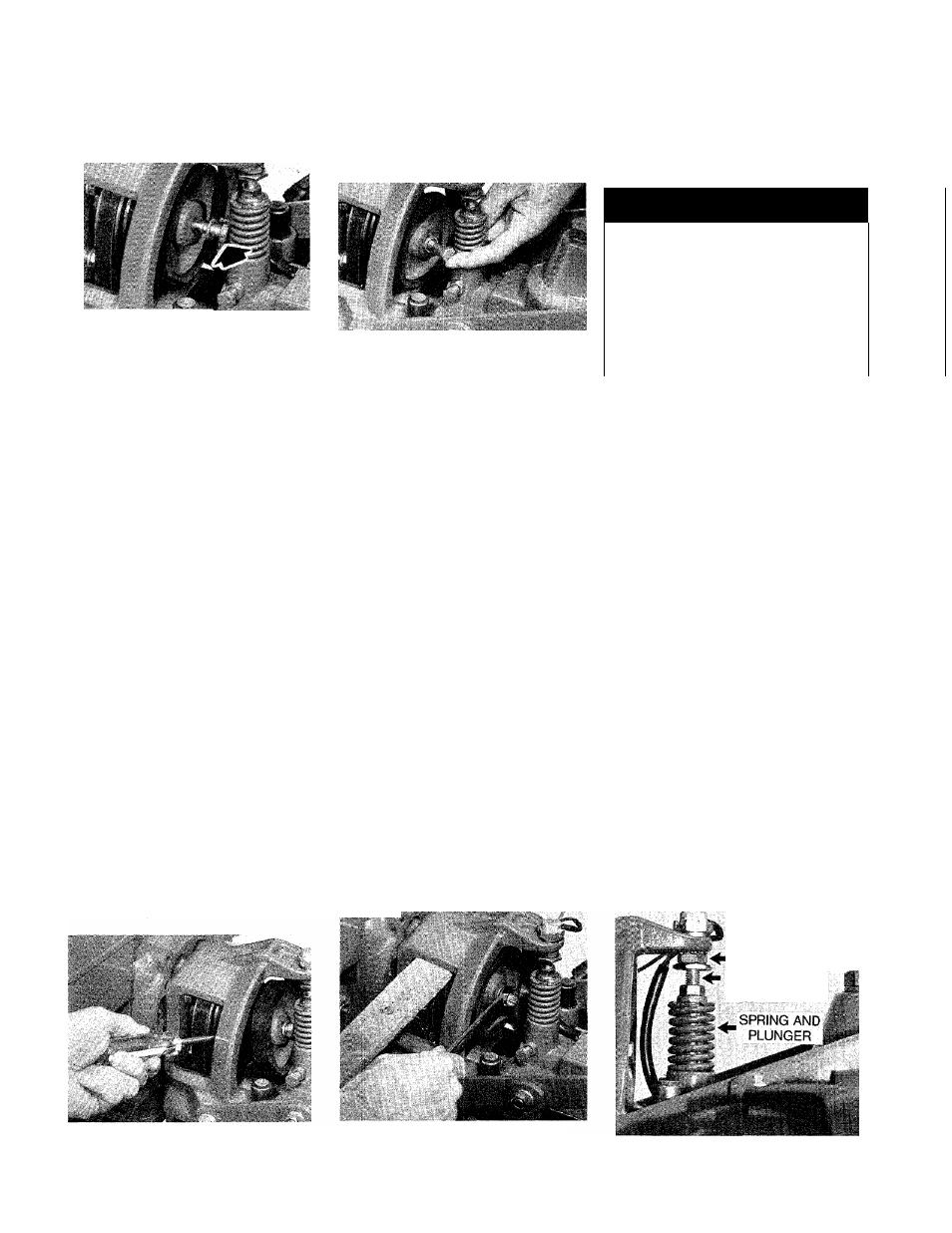
6-29: Loosen, but do not remove bolt.
2. To prevent the reverse disc and
its mounting bolt from turning as
you try to remove the bolt, first
place a 5/16-inch thick board be
tween the top of the engine pulley
(avoid the disc and drive belt) and
the cast iron engine mount (Photo
6-28).
3. Working from the left side of the
tiller, place the boxed end of a
9/16-inch wrench on the mounting
bolt. Then pull up hard on the stick
and push down sharply on the
wrench. This sharp push with the
wrench should break the bolt loose
without also causing the pulley
to turn.
4. Loosen the bolt until it just tou
ches the reverse spring and plunger
assembly (Photo 6-29). Don’t try to
remove the bolt just yet.
5. Use a screwdriver to separate
the disc from the engine pulley
(Photo 6-30).
6. Slide the disc out until it tou
ches the head of the mounting bolt.
Then angle the disc a little to the
left and remove the bolt and its
lockwasher (Photo 6-31). Now
remove the disc.
6-31: Angle disc to remove or install
mounting bolt.
To replace the reverse disc:
1. One side of the disc has a
raised shoulder in its center. When
installing the disc, this shoulder
must be facing away from the en
gine pulley.
2. With the Wheels/Tines/PTO
Drive Lever in “NEUTRAL”, insert
the disc in front of the engine pul
ley and angle it as shown in Photo
6-31. Put the lockwasher on the
bolt and insert the bolt through the
disc.
3. Hold the disc against the engine
pulley and hand-tighten the bolt as
far as you can.
4. To fully tighten the bolt, place
the 5/16-inch thick board in be
tween the top of the engine pulley
(avoid the disc and belt) and the
engine mount (Photo 6-32). Now
pull up hard on the board while
you tighten the bolt with the wrench.
5. Check for correct reverse drive
operation by referring to the fol
lowing instructions.
A WARNING
To help avoid personal injury, stop
the engine, remove the electric
start key, disconnect the spark
plug wire, and let the engine and
muffler cool before inspeoting or
adjusting the reverse drive
components.
When the Wheels/Tines/PTO
Drive Lever is shifted into
“REVERSE”, the engine and the
engine mount move down to press
on the reverse adjustment bolt
(Photo 6-33). This action com
presses the reverse spring and
plunger assembly, requiring you to
hold the lever up in “REVERSE”.
When you let go of the lever, the
spring automatically pushes the
lever back into “NEUTRAL”.
The spring and plunger assem
bly is designed to prevent the re
verse disc from making contact with
the transmission pulley until you
decide to shift into “REVERSE”.
When the lever is in “NEUTRAL”,
the switch body on the bottom of
the engine mount tab should be
resting squarely on top of the re
verse adjustment bolt (Photo 6-33).
The reverse adjustment bolt can
be adjusted up or down to correct
a number of reverse drive operat
ing problems, as explained next.
■ SWITCH BODY
ADJUSTMENT
BOLT
6-30: Use screwdriver to separate
disc from engine pulley.
6-32: Wedge pulley with board and
tighten bolt.
6-33: Spring and plunger assembly.
45