Important, To replace the tine attachment – Troy-Bilt 8 HP User Manual
Page 35
Attention! The text in this document has been recognized automatically. To view the original document, you can use the "Original mode".
ENGINE THROTTLE
%. rC FORWARD INTERLOCK
LEVERS
WHEELS/TINES/PTO
DRIVE LEVER
I
WHEEL SPEED LEVER
J
j j - / .
TINES/PTO ■
DLUTCH LEVER ^
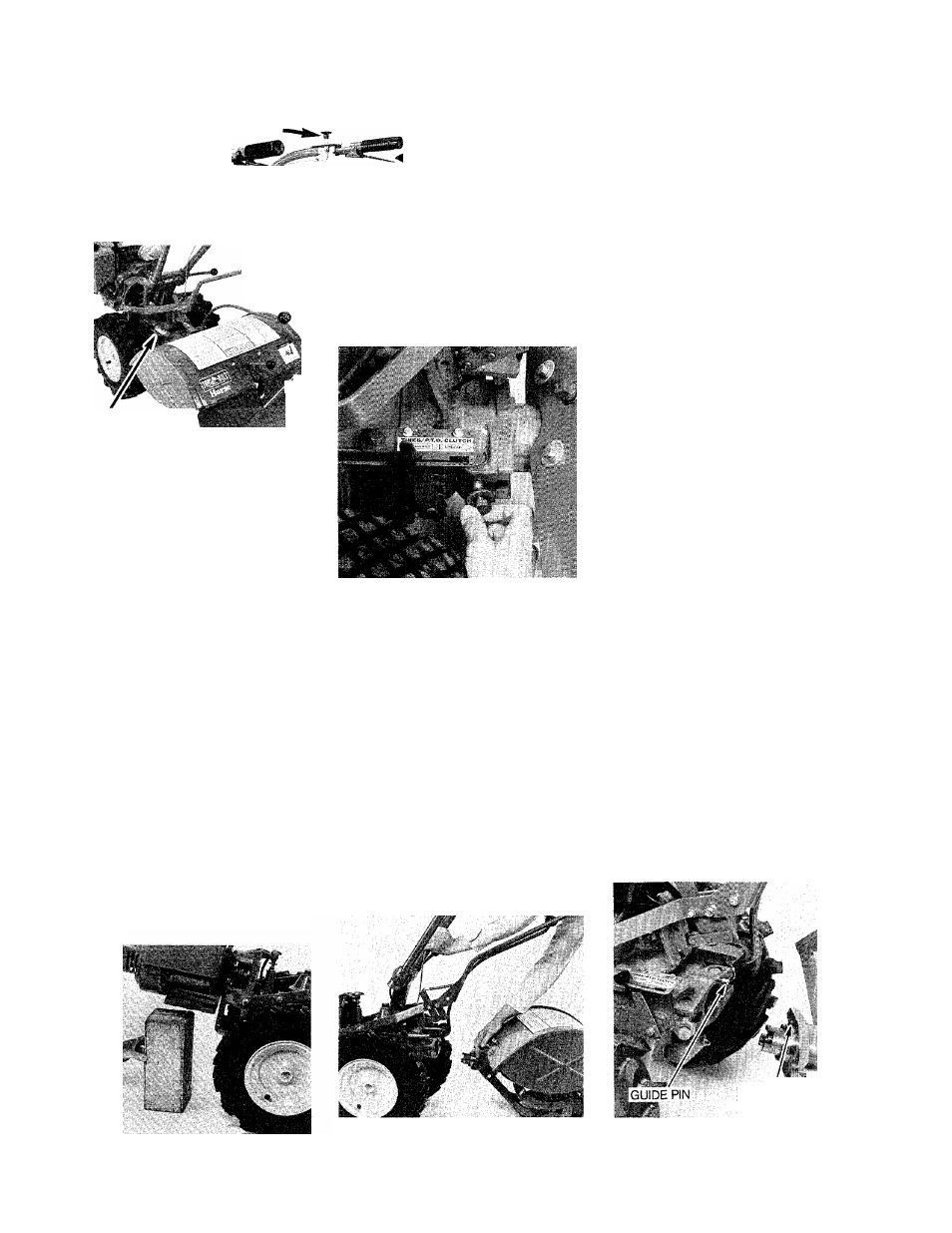
5-4: PTO Power Unit controls.
4. Place the Tines/PTO Clutch
Lever in “DISENGAGE” (Photo
5-4).
5. Place the Wheel Speed Lever in
“FREE WHEEL” (Photo 5-4).
6. Place a sturdy support under
the engine, or use the Kickstand
on your bumper (if so equipped) to
prevent the engine from tipping
down when the tine attachment is
removed. See Photo 5-5.
7. Using a %-inch wrench, loosen
the two swing-bolts that connect
the power unit transmission to the
tine attachment and swing the boits
outward. See Photo 5-6. NOTE: An
extra-iong (13") PTO Wrench is
avaiiable from our Parts Depart
ment. This heavy-duty wrench (Part
No. 2005) makes it quick and easy
to remove and replace the tine
attachment.
5-6: Move swing-bolts outward.
8. With one hand on the handle
bars of the power unit, tip the unit
forward about an inch whiie you
puil the tine attachment back a
short distance. This reieases the
guide pin on the power unit from
the guide pin mounting hole in the
tine attachment. See Photos 5-7
and 5-8.
IMPORTANT
Aiways store your tine attachment
in a levei position to avoid iosing
oil from the breather vent, locaieri
in the top of the dipstick.
9. Place the dust cap (supplied
with certain attachments), or some
plastic wrapping over the “dog”
clutch coupling of the tine attach
ment to prevent dirt and grime from
accumulating on the coupling.
10. The power unit is now ready to
accept other powered or non-
powered attachments. Refer to the
Owner/Operator Manual supplied
with each attachment for specific
instructions on how to install and
operate the attachment.
To replace the tine attachment:
1. Follow Steps 1-5 of the pre
vious tine attachment removal
instructions.
2. Place the two swing-bolts on
the power unit in the outward posi
tion, making sure that the washers
on the bolts are next to the bolt
heads.
3. Roll the power unit back to the
tine attachment and either put
down the optional Kickstand or
place a sturdy support under the
engine.
4. Remove the dust cap or protec
tive wrapping from the clutch cou
pling on the tine attachment.
5. Carefully align the alignment pin
on the power unit with the align
ment hole on the tine attachment
and bring the two units together
(Photo 5-8).
5-5: Block up engine.
5-7: Lift handlebars while pulling at
tachment away from power unit.
MOUNTING HOLE
5-8: Aiign guide pin with mounting
hole.
33