External connections, External connections -10, User’s manual – Asus P/I-P55SP3AV User Manual
Page 71: P/i-p55sp3av
Attention! The text in this document has been recognized automatically. To view the original document, you can use the "Original mode".
P/I-P55SP3AV
User’s Manual
External Connections
There are several connectors on the board for switches and indicator lights from
the system case. The connectors are made of the same components as the
jumper switches. There are also connectors for the on-board I/O ports and a
system power supply.
Connector Block:
SMI Switch Connector for a Suspend switch lead.
Reset Switch Connector for a Reset switch lead.
Speaker
Connector for a system case speaker lead.
Keylock
Connector for a keyboard lock and Power-On LED.
Turbo Switch
Connector for a Turbo Switch. No function on this mainboard.
Turbo LED
Connector for a Turbo LED.
[Note: The Turbo feature is not supported on this mainboard. A Turbo LED will
light all the time if connected, but a switch will have no effect.]
PS/2 Mouse Connector for a PS/2 mouse port lead.
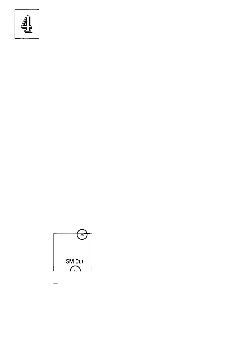
JP10 SM Out Connector for a power management lead from a green device.
JP17 Fan Power Connector for cooling fan +12V power lead.
Connector for an IDE activity LED.
Connector for a digital volume control module
Connector for an IrDA-compliant infrared port module
PS/2 Mouse
connector (or port)
Please Note:
The battery that supports the onboard
CMOS memory (where the system
configuration record is stored) is a 3-
Fan Power,
volt Lithium cell. It has a life expectancy
IDE LEO, M ""I I
of approximately 7 years. Replace it by
Case, IR &
--------1 lifting up the retaining clip and pulling
Volume Control ^
battery out. Insert a new battery
connectors
CMOS Battery
with the writing side face up.
JP29 IDE LED
JP30VOI Control
JP31 IR
4 - 1 0