5 scraper blade, 6 auger rubber, Scraper blade -6 – Ariens 932 Series User Manual
Page 39: Auger rubber -6, Auger/impeller - discharge chute
Attention! The text in this document has been recognized automatically. To view the original document, you can use the "Original mode".
Auger/Impeller - Discharge Chute
Adjust attachment clutch cable with clutch
disengaged. Pull clutch chain taught and con
nect chain link to spring. Spring should extend
approximately 3/8” with clutch engaged. With
clutch disengaged, clutch arm should fall to its
maximum down position.
6.5 Scraper Blade
IMPORTANT: If blade wears too far, auger/im-
peller housing may be damaged.
Scraper blade on models with runners is ad
justable to compensate for wear.
To adjust scraper blade, tip unit back onto
handlebar, support housing, and loosen nuts
retaining blade. With runners adjusted to their
full up position, reposition scraper blade down,
flush with runners, and tighten lock nuts.
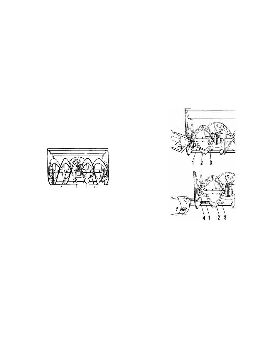
3 1
Shear Bolt
Scraper Blade
Auger
Figure 6-5: Shear Bolts and Scraper Blade
On 2 + 2 models, scraper blade is adjustable
to compensate for wear and to control traction.
Best operation occurs if scraper blade edge
leaves a fine dusting of snow with auger tracks
(auger propels unit). Adjust scraper blade
equally its full length if machine does not
scrape cleanly or if machine does not drive for
ward properly.
To adjust scraper blade, tip unit back and rest
unit on handlebar. Loosen nuts on carriage
bolts along scraper support. If unit does not
scrape cleanly, move scraper blade forward. If
unit does not drive forward and scraper blade
drags, move scraper blade to the rear.
NOTE: Be sure scraper support is fully engaged
in groove of scraper blade. Tighten hardware
and test unit. Repeat adjustment as required
until proper operation is obtained.
6.6 Auger Rubber
On 2 -I- 2 models, the rubber edges on auger
will wear and require replacement after a
period of use. Two replacement kits are
available.
1. Drill
{V
a
”
or larger)
2. Auger
3. Rubber Edge
4. Access Hole
Figure 6-6: Auger Rubber Replacement
The second procedure replaces the rubber
edges and requires the drilling off of rivets
holding old rubber edge to segment by means
of a 1/4” diameter or larger drill bit. (An access
hole is provided on sides of auger/impeller
housing for access to outer rivets.) Then posi
tioning new rubber edge on segment and se
curing with bolts, flat washers and lock nuts.
The first procedure replaces both the right and
left augers requiring the removal of the augers
and impeller from the auger/impeller housing.
Then removing augers from auger shafts, plac
ing new augers onto auger shafts and reas
sembling unit.
I
NOTE: After repiacement of auger rubber
edges, adjust scraper biade per instruction in
Adjustments Section.
6-6