2 friction wheel removal, 3 drive plate removal, 2 friction wheei removal -4 – Ariens 932 Series User Manual
Page 31: 3 drive plate removal -4, Friction wheei drive, 1 introduction, 4 clutch fork removal
Attention! The text in this document has been recognized automatically. To view the original document, you can use the "Original mode".
Friction Wheei Drive
5.1 Introduction
A
WARNING: Remove wire from spark plug
before attempting any repair or adjust
ment procedures.
When unit is tipped onto housing, remove
enough fuel so that no spillage will occur,
block securely and remove bottom cover.
A
WARNING: Gasoline is highly flammable
and its vapors are explosive. Handle with
care.
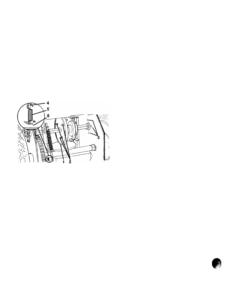
1. Friction Wheel
2. Cap Screw
3. Bearing Flange Screws
4. Clutch Fork
5. Extension Spring
6. Frame
Figure 5-3: Friction Wheel
5.2 Friction Wheel Removal
Tip unit onto housing and remove bottom
cover by removing four Cap screws.
Remove bearing flange screws on right hand
side of frame and remove bearing flange.
Remove hairpin cotter from traction clutch rod,
pull rod from clutch fork arm and tip up and out
of way.
Slide friction wheel assembly and hex shaft to
right until left end of hex shaft comes free of
left bearing. Slip assembly back to left and pull
forward out of frame.
Remove three cap screws securing friction
wheel to hub and remove friction wheel.
Secure new friction wheel onto hub with three
cap screws and torque cap screws to 8-10 foot
pounds.
Assemble using reverse procedure.
5.3 Drive Plate Removal
Remove drive plate return spring and bearing
flange from frame opposite axle gear, and
remove friction wheel.
Assemble using reverse procedure.
5.4 Clutch Fork Removal
Remove cap from outside of frame and cotter
pin from clutch fork rod. Remove clutch fork.
Inspect parts for wear or replacement and
assemble using reverse procedure.
NOTE: Position friction wheel hub in forks. Be
sure washers are in place on bearing flange
pins. Slide hex shaft to left and into left bear
ing with flat washers in position. Pinion gear
must mesh with large gear.
Remove auger/impeller housing and bottom
cover according to instructions in Auger/-
Impeller Section.
Remove attachment drive belt according to in
structions in Belt Drive Section and remove ex
tension springs from idlers.
Remove set screws from attachment pulley
hub and remove attachment pulley and hub.
Remove drive plate assembly, and remove fric
tion plate and bearing flange from assembly by
removing snap ring.
NOTE: Apply Loctite Anti-Sieze to hex end of
shaft before placing friction plate back onto
assembly.
Remove friction wheel assembly according to
instructions in Friction Wheel Removal Sec
tion and remove axle.
5-4