Assembly – Sears 113.298141 User Manual
Page 7
Attention! The text in this document has been recognized automatically. To view the original document, you can use the "Original mode".
Item Part Name
Qty.
Z
Hex Nut, 5/16-18
(approx, dia. of hole 5/16 in.) ........ ........... 9
Z
Hex Nut, 1/4-20
(approx, dia. of hole 1/4 in.)
. . . . . . . .
........ 2
AA
Lockwasher, 5/16 In, External Type
(approx, dia. of hole 5/16 in.) .................... 11
AA
Lockwasher, 1/4 in. External Type
(approx, dia. of hole 1/4 in.) ...................... 2
AA
Lockwasher No. 1() External Type
(approx, dia. of hole 3/16 in.) ............
.. ... 1
AB
Carriage Bolt, 5/16-18 x 3/4 in. long .., ........ 4
AC
Rip Fence Guide Bar Spacer ................ ........ 2
AD
Wire Tie................................................ ........... 2
AE
Thumbscrew, 5/16-18 x 1 in. long . . . . . . ........ 1
A F
Screw Pan Hd. 10-32 x 3/4 ............................. 1
AG
Flat Washer (dia. of hole 21/64) ................... 2
The following parts are included with Model 113,298031 and
113.298151.
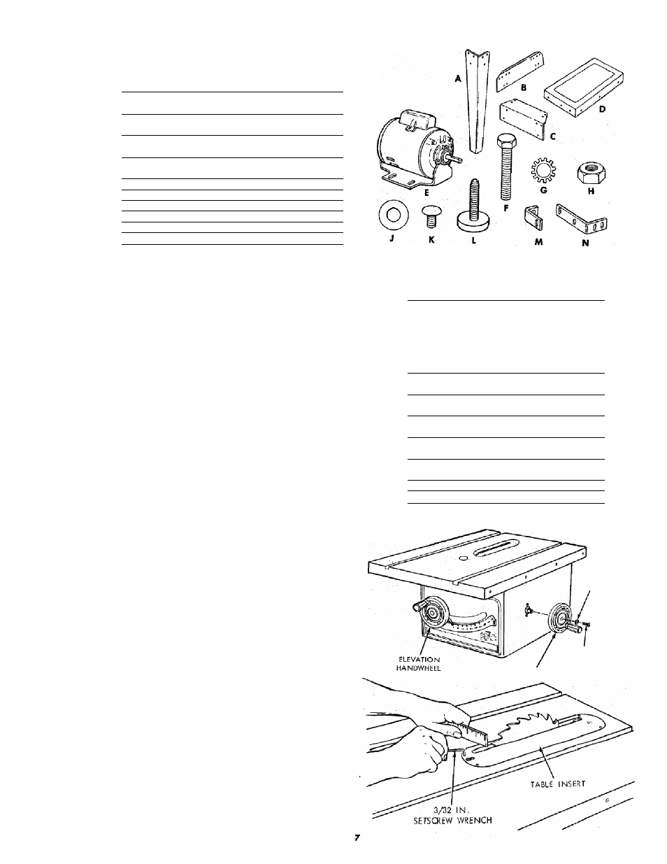
A Leg .............................. ................................................................
S Side Stiffener .............................................................................
C End Stiffener...............................................................................
D Table Extension (113.298031) ....................................... 2
Table Extension <113.298151) ...................................
E Motor .................................................................. ....................
Pkg. of Miscellaneous Small Parts, No, 62752 for Legs
Consisting of the Following:
F Hex Head Screw 5/16-18 X 1-1/4 in. long .
G Lockwasher, 1/4 in. External Type
(approx, dia. of hole 1/4 in.)........................................ 24
G Lockwasher, 5/16 in. External Type
(approx, dia. of hole 5/16 in.) ................ ............
H
Hex Nut, 1/4-20
(approx, dia. of hole 1/4 in.) ...................................... 24
H
Hex Nut, 5/16-18
(approx, dia. of hole 5/16 in.)..............................
H
Hex Nut, 1/2-13
(approx, dia. of hole 1/2 in.) ...............................
J
Flat Washer (dia. of hole, 11/32 in.).............................. 8
Item
Part Name
Qty.
4
K
Truss Head Screw, 1/4-20 x 5/8 In. long
2
(top of screw is rounded) .......................................... . 24
2
2
1
1
gs
L
Leveling Foot ................................................................
Pkg. of Miscellaneous Small Parts No. 62745 for
Table Extensions (1 aa. for Model 113.298151,
2ea. forModeni3.238031)
Consisting of the following:
. 4
F
Hex Hd. Screw, 5/16-18 X 1-1/4 in. long ________ . 4
4
G
Lockwasher, External Type
(approx, dia. of hole 1/4 in.) ...................................... . 8
24
G
Lockwasher, External Type
(approx.dia.ofholeS/IBin.) .......................................... . 4
4
H
Hex Nut, 1/4-20
(approx, dia. of hole 1/4 in.) ...................................... . 8
24
H
Hex Nut, 5/16-18
(approx, dia. of hole 5/16 in.).................................... . 8
4
K
Truss Head Screw, 1/4-20 x 1 in. long
(top of screw is rounded) ............................................ . 8
8
M
Corner Stiffener Bracket ............................................... . 2
8
N
Corner Support Bracket ........ ........................ .............. . 2
ASSEMBLY
Before mounting the saw on legs, a stand or a bench, the
Table Insert and Blade Squareness must be checked at this
time.
IWSTALLIIVIG HANDWHEELS
1, Line up FLAT SPOTS on shaft and handwheel, push
handwheel onto shaft. Install screw and lockwasher to
lock handwheel on shaft.
CHECKING TABLE INSERT
2. Insert should be flush with table top. Check as shown.
Loosen flat head screw that holds insert and adjust the
four set screws as necessary. Tighten flat head screw.
Do not tighten screw to the point where it deflects the
insert.
LOCKWASHER
10-32 X 3/4 IN.
PAN HEAD SCREW
TILT HANDWHEEL