Installing blade guard – Sears 113.298141 User Manual
Page 14
Attention! The text in this document has been recognized automatically. To view the original document, you can use the "Original mode".
2
.
3.
4.
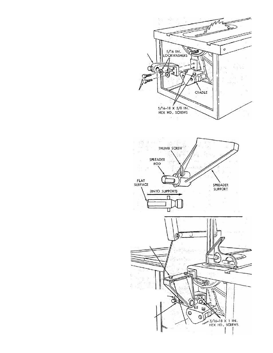
INSTALLING BLADE GUARD
From among the loose parts, find
2 Hex Head Screws, 1/4 - 20 x 5/8 in. long
2 Hex Head Screws, 5/16 -18 x 5/8 in. long
2 Hex Head Screws, 5/16-18 X I in. long .
2 Hex Nuts, 1/4 -20
(approx, dia. of hole 1/4 in.)
2 Lockwashers, 1/4 in, External Type
(approx, dia. of hole 1/4 in.)
2 Lockwashers, 5/16 in. External Type
(approx, dia. of hole 5/16 in.)
1 Thumbscrew
Guard Support
Spreader Support
Spreader Rod
Lower the blade.
Screw the two MOTOR BASE GLAMP SCREWS part
way into cradle.
Attach GUARD SUPPORT., , DO NOT TIGHTEN
screws.
GUARD SUPPORT
5/16-18 X
5/8 IN,
HEX HD,'
SCREW
5/16-18 X 1 IN.
HEX HD. SCREW
5.
Insert SPREADER ROD into SPREADER SUPPORT
until pin fits into notch. Insert Thumbscrew and tighten
it
-
■
6.
Slide SPREADER ROD into GUARD SUPPORT until
left end of ROD extends approximately 14 inch beyond
edge of SUPPORT ... Snug up Hex Head Screw in
SUPPORT.
7.
Attach SPREADER to SPREADER SUPPORT so that
screws are all the way back in the SLOTS of SUPPORT
... tighten screws.
8.
Raise ANTIKICKBACK PAWL (hold it in place with a
piece of masking tape)
... align spreader SQUARE to table
NOTE: The framing (or combination) square must be
"true" — see start of "assembly and alignment':' section
on page 6 for checking method.
... Tighten both 5/16-18 x 1 in. HEX HEAD SCREWS.
1/4-20 HEX
HD. SCREW
1/4 IN. LOCKWASHER
1/4-20 HEX NUT
END OF ROD
1/4 INCH TO LEFT
OF EDGE OF
SUPPORT
GUARD
SUPPORT
SCREWS ALL THE
'WAY BACK IN SLOTS
IN SUPPORT
14