Step 3 — field fabricate ductwork — secure all, Step 4 — make unit duct connections — unit, Step 5 — install flue hood and wind baffle – Carrier 48TJ016-028 User Manual
Page 9: Step 3 — field fabricate ductwork, Step 4, Make unit duct connections, Step 6, Trap condensate drain
Attention! The text in this document has been recognized automatically. To view the original document, you can use the "Original mode".
step 3 — Field Fabricate Ductwork
— Secure all
ducts to building stnjcture. Use flexible duct connectors be
tween unit and ducts as required. Insulate and weatlierproof all
external ductwork, joints, and roof openings with counter
flashing and mastic in accordance with applicable codes.
Ducts passing through an unconditioned space must be in
sulated and covered with a vapor barrier.
Step 4
—
Make Unit Duct Connections
— Unit
is shipped for thra-the-bottom duct connections. Ductwork
openings are shown in Fig. 1, 4, and 5. Duct connections are
shown in Fig. 6. Field-fabricated concentric ductwork may be
connected as shown in Fig. 7 and 8. Attach all ductwork to roof
curb and roof cuit) basepans.
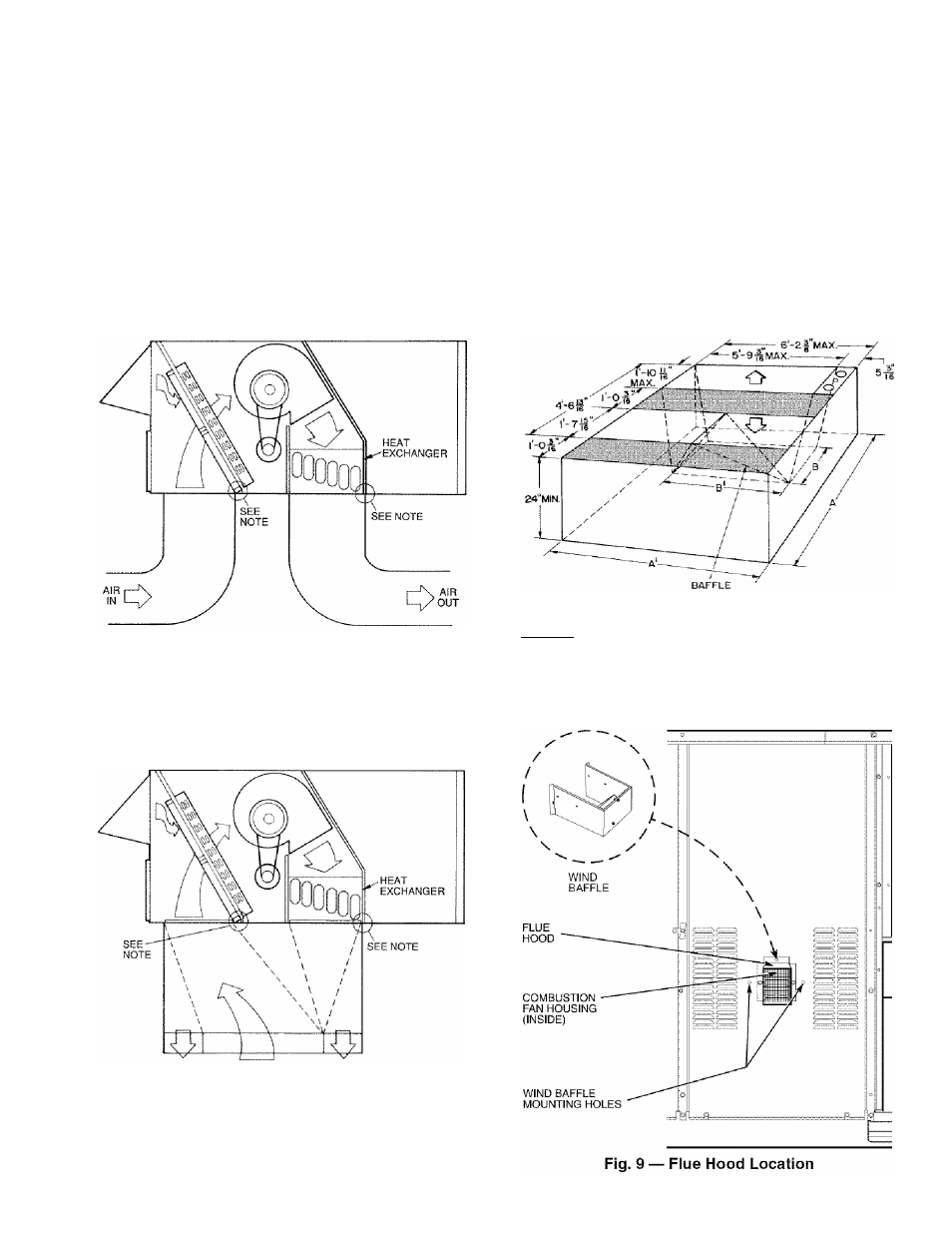
Step 5 — Install Flue Hood and Wind Baffle —
Flue hood and wind baffle are shipped secured under main
control box. To install, secure flue hood to access panel. See
Fig. 9. The wind baffle is then installed over the flue hood.
NOTE: When properly installed, flue hood will line up with
combustion tan housing. See Fig. 10.
Step 6
—
Trap Condensate Drain
— See Fig.
1 1
for drain location. One ^
4
-in. half coupling is provided inside
unit evaporator section for condensate drain connection. An
S'A-in.
X
^
4
-in. diameter and 2-in.
x
diameter pipe nip
ple, coupled to standard V
4
-in. diameter elbows, provide a
straight path down through hole in unit base rtiils (see Fig. 12).
A trap at least 4-in. deep must be used.
NOTE: Do not drill in this area; damage to basepan may result in
water leak.
Fig. 6 — Air Distribution — Thru-the-Bottom
NOTE:
Dimensions
A,
A',
and
B'
are
obtained
trom
field-supplied
ceiling diffuser.
I
r| Shaded area indicates block-off panels.
Fig. 8 — Concentric Duct Details
AIR OUT
AIR IN
AIR OUT
NOTE: Do not drill in this area; damage to basepan may result in
water leak.
Fig. 7 — Concentric Duct Air Distribution