Step 10 — make outdoor-air inlet adjustments, Standard 25% outdoor-air section details, Step 11 — install outdoor-air hood – Carrier 48TJ016-028 User Manual
Page 14
Attention! The text in this document has been recognized automatically. To view the original document, you can use the "Original mode".
step 10 — Make Outdoor-Air Inlet Adjust
ments
MANUAL OUTDOOR-AIR DAMPER ^ All units (except
those equipped with a factoiy-instiilled economizer) have a
manual outdoor-air damper to provide ventilation air.
Damper can be preset to admit up to 25% outdoor air into
return-£iir compartment. To adjust, loosen securing screws and
move damper to desired setting, tlien retighten screws to secure
diunper (see Fig. 17).
25% ADJUSTABLE
AIR DAMPER
Fig. 17
SECURING SCREWS
Standard 25% Outdoor-Air
Section Details
Step 11 — Install Outdoor-Air Hood
IMPORTANT: If the unit is equipped with the optional
EconoMi$eiTV, move the outdoor air temperature sensor
prior to installing the outdoor air hood. See the Optional
EconoMi$eiTV and EconoMi$er2 section for more details.
Tlie outdoor- air hood is common to 25% air ventilation and
economizer. If EconoMi$erIV is used, all electrical connec
tions have been made and adjusted at the factory. Assemble
and install hood in the field.
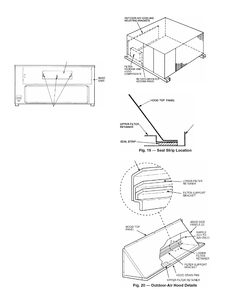
NOTE: Tlie hood top panel, upper and lower filter rettdners,
hood drain pan, baffle (size 024 and 028), and filter support
bracket iu'e secured opposite the condenser end of the unit. The
screens, hood side panels, remaining section of filter support
bracket, seal strip, and hai'dware are in a package located
inside the return-air filter access panel (Fig. 18).
1. Attach seal strip to upper filter retainer. See Fig. 19.
2. Assemble hood top panel, side panels, upper filter retain
er, and drain pan (see Fig. 20).
.2. Secure lower filter retainer and support bracket to unit.
See Fig. 20. Leave screws loose on size 024 and 028
units.
4. Slide baffle (size 024 and 028) behind lower filter retainer
and tighten screws.
5. Loosen sheet metal screws for top panel of base unit
located above outdoor-air inlet opening, and remove
screws for hood side panels located on the sides of the
outdoor-air inlet opening.
6. Match notches in hood top panel to unit top panel screws.
Insert hood flange between top panel flange and unit.
Tighten screws.
7. Hold hood side panel flanges flat against unit, and instiill
screws removed in Step 5.
8. Inseit outdooi'-air inlet screens and spacer in channel cre
ated by lower filter retainer and filter support bracket.
Fig. 18 — Outdoor-Air Hood Component Location
HOOD DRAIN
PAN
BAFFLE
14