Hp m plcs – Carrier 48TJ016-028 User Manual
Page 5
Attention! The text in this document has been recognized automatically. To view the original document, you can use the "Original mode".
UNIT
STD UNIT
WEIGHT
ECONOMIZER
WEIGHT
CORNER
A
CORNER
B
CORNER
C
CORNER
D
DIMA
DIM B
DIM C
lb
kg
lb
kg
lb
kg
lb
kg
lb
kg
lb
kg
ft-in.
mm
ft-in.
mm ft-in.
mm
48TJD,
TJF016
1650
748
90
41
423
192
386
175
403
183
438
199
3-5
1041
3-5
1041
1-10
559
48TJD,
TJF020
1800
816
90
41
432
196
410
186
461
209
472
214
3-3
991
3-7
1092
1-8
508
HP m PLCS
0 ' ■ 3 T 3 S “ ^ Í
1993 I
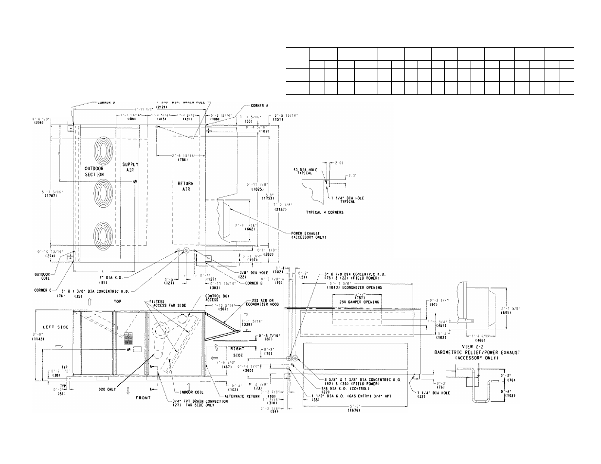
NOTES:
1. Refer to print for roof curb accessory dimensions.
2. Dimensions in ( ) are in miiiimeters.
Center of Gravity,
o Direction of airflow.
5. Ductwork to be attached to accessory roof curb only.
6. Minimum clearance:
• Rear: 7'-0" (2134) for coil removal. This dimension can be reduced to
4'-0" (1219) if conditions permit coil removal from the top.
• 4'-0" (1219) to combustible surfaces, all four sides (includes between
units).
• Left side; 4'-0" (1219) for proper condenser coil airflow.
• Front: 4'-0" (1219) for control box access.
• Right side: 4'-0" (1219) for proper operation of damper and power
exhaust if so equipped.
• Top: 6'-0" (1829) to assure proper condenser fan operation.
• Bottom: 14" (356) to combustible surfaces (when not using curb).
• Control box side; 3'-0" (914) to ungrounded surfaces, non-combustible.
• Control box side: 3'-6" (1067) to block or concrete walls, or other
grounded surfaces.
• Local codes or jurisdiction may prevail.
7. With the exception of clearance for the condenser coil and the damper/
power exhaust as stated in Note #6, a removable fence or barricade
requires no clearance.
8. Dimensions are from outside of corner post. Allow O'-s/ie" (8) on each side
for top cover drip edge.
SECTION A-A
Fig. 4— Base Unit Dimensions; 48TJ016,020