Fig. 23, Motormaster v control, A 0j|^||y|q – Carrier 48TJ016-028 User Manual
Page 16
Attention! The text in this document has been recognized automatically. To view the original document, you can use the "Original mode".
MOTORMASTER®
V
CONTROL
INSTALLATION
(48TJ024,028 UNITS)
Install Lield-Fabricated Wind Baffles — Wind baffles must
be field-fabricated for all units to ensure proper cooling cycle
operation at low ambient temperatures. See Fig. 21 for baffle
details. Use 20-gage, galvanized sheet metal, or similar
coito
-
sion-resistant metal for baffles. Use field-supplied screws to at
tach baffles to unit. Screws should be ‘A-in. diameter and
5/s-in. long. Drill required screw holes for mounting baffles.
A 0j|^||Y|Q||
To avoid dmnage to the refrigerant coils and electrical com
ponents, use recommended screw sizes only. Use cru'e
when diilling holes.
FR<3M FUSE BLOCK
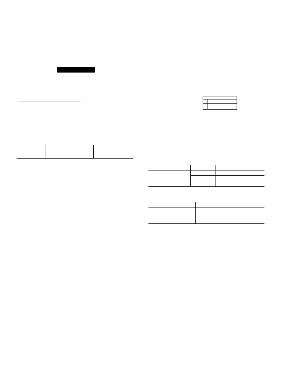
Install Motormaster V Controls — Tlie Motormaster V
(MMV) control is a motor speed control device which adjusts
condenser fan motor speed in response to declining liquid re
frigerant pressure. A properly applied Motormaster V control
extends the operating range of air-conditioning systems and
permits operation at lower outdoor ambient temperatures.
Tlie minimum iunbient temperatures at which the unit will
operate are:
TEMPERATURE OPERATING LIMÌTS — F°
standard
Unit with
Unit with
Unit
Low Ambient Kit
MMV Control
40
25
-20
To operate down to the ambient temperatures listed,
Motomiaster V controls (Fig. 23) must be added. Field-fabricat
ed and installed wind baffles iu'e also required for iill units (see
Fig. 21). The Motormaster V control permits operation of the
unit to an ambient temperature of-20 F. Tlie control regulates the
speed of 3-phase fan motors that aie compatible with the control.
Tliese motors are factoiy installed.
See Table 6 for the Motormaster V control accessoiy pack
age usage. Table 7 shows applicable voltages and motors.
Replacement of motor or fan blade IS NOT REQUIRED ON
CURRENT PRODUCTION UNITS since the control is
compatible with the factoiy-installed fan motors. Only field
wiring control is required
Install the Motormaster V control per instiuctions supplied
with accessoiy.
Ó O Ò O Ó
TO PRESSURE^
TRANSDUCER
U
U L3
12 13Ai
256
I
n
io/-\
IflrtDfVÌÓnrTnhDnrvnfìDITri
/;n 7О О3 B-
O Q O O O
C E [ 3
G
5
o
Fig. 23
TO MOTOR(S)
Motormaster V Control
Table 6 — Motormaster V Control Package Usage
UNIT
VOLTAGE
ITEM DESCRIPTION
208/230
CRLOWAIVIB015A00
48TJ024,028
460
CRLOWAÌVIB016A00
575
CRLOWAW1B017A00
Table 7 — Applicable Voltages and Motors
VOLTAGE
COMPATIBLE MOTOR
208/230-3-60
HD52AK654
460-3-60
HD52AK654
575-3-60
HD52GE576
16