Carrier 58DRC User Manual
Installation, start-up and service instructions, 58drc counterflow gas-fired furnaces
Attention! The text in this document has been recognized automatically. To view the original document, you can use the "Original mode".
HEATING & COOLING
58DRC
Counterflow Gas-Fired Furnaces
Installation, Start-Up and Service Instructions
for Sizes 045-095
NOTE. Energy Guide tag may be removed
from furnace when installation is complete.
G
efficiency
RATING
CGRTIFIED
ama
INTRODUCTION
Before installing the furnace, refer to Procedures for
Gas-Fired Furnaces (packaged with the equipment) for
information concerning combustion, venting, piping,
and
other
standard
installation
practices.
Further
reference is made to the current edition of the
National Fuel Gas Code, NFPA54-1984/ANSI Z223.1-
1984.
Each furnace is shipped from the factory completely
assembled with multispeed direct-drive blower and wired
ready for counterflow indoor heating installation only.
All sizes feature a printed-circuit board control center
with easy-to-read, low-voltage terminal strip to ensure
proper connections.
A
CAUTION
Do not install furnace in a corrosive or contami
nated atmosphere. Make sure all combustion and
circulating air requirements listed in Procedures
for Gas-Fired Furnaces are adhered to, in addition
to all local codes and ordinances.
A
CAUTION
Do not block openings in front of furnace or on
furnace top along side vent pipe. These openings pro
vide air for combustion and ventilation. Never store
anything on or in contact with furnace, such as:
aerosol cans, rags, brooms and mops, cleaning tools
and aids, powders, bleaches, waxes, plastic items,
gasoline, kerosene, lighter fluids, cleaning fluids,
thinners, painting compounds or paper products.
The design of the counterflow gas-fired furnace is
A.G.A certified for installation on combustible flooring
(with optional floor base), in alcoves, basements, closets
or utility rooms. This furnace line is not A.G.A. certified
for installation in a mobile home, recreation vehicle, or
outdoors
Installation Procedures:
Page
Inspection.......................................................................... *
Location, Ventilation and Air
for Combustion................................................................*
Gas Piping......................................................................... *
Venting..............................................................................*
Supply-Air Plenum Installation.........................................1
Electrical Connections.......................................................3
Sequence of Operation.......................................................4
Filter Arrangement............................................................ 5
Start-Up and Adjustment................................................... 6
Care and Maintenance....................................................... 6
*Refer to appropiiate sections in Pioceduies foi Gas-Fired Furnaces
packed with this furnace
For accessory installation details, refer to applicable
installation literature.
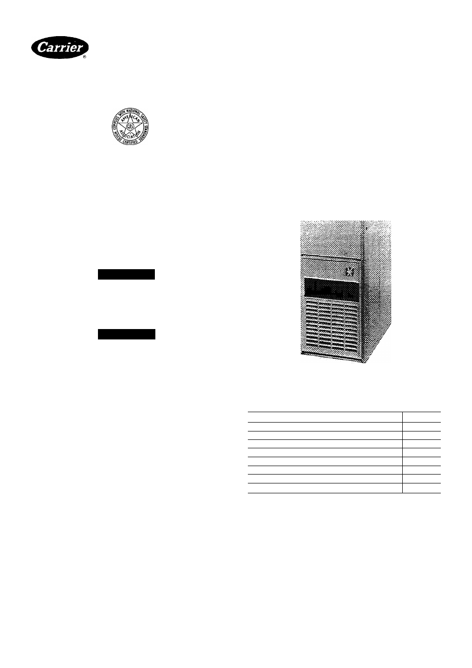
Fig. 1 — Model 58DRC
Table 1 — Clearances (in.)
SIZE 58DRC
ALL
Single-Wall Vent
1
Type-BI Double-Wall Vent
1
Back
0
Top of Plenum
1
Single-Wall
6
......... .. Type-B1 Double-Wall
1
„ Combustion Air
6
’ Service
30
NOTE. Some furnaces are shipped with paper across the
supply-air outlet. Remove the paper before installing
furnace.
INSTALLATION
Supply-Air Plenum Installation
INSTALLATION ON A CONCRETE SLAB
1 See Fig. 2 for dimensions and location of supply air
opening in furnace bottom
Manufacturer reserves the right to discontinue, or change at any time, specifications or designs without notice and without incurring obiigations.
Bookll 14
PC101
Catalog No 535-843
PrintedinUSA
Form58DRC-1SI
Pg 1
7-85
Replaces:New
For replacement items use Carrier Specified Parts
Tab |6al8a