Operating sequence, Table 25 — evaporator-fan motor data – Carrier 48TJ016-028 User Manual
Page 36
Attention! The text in this document has been recognized automatically. To view the original document, you can use the "Original mode".
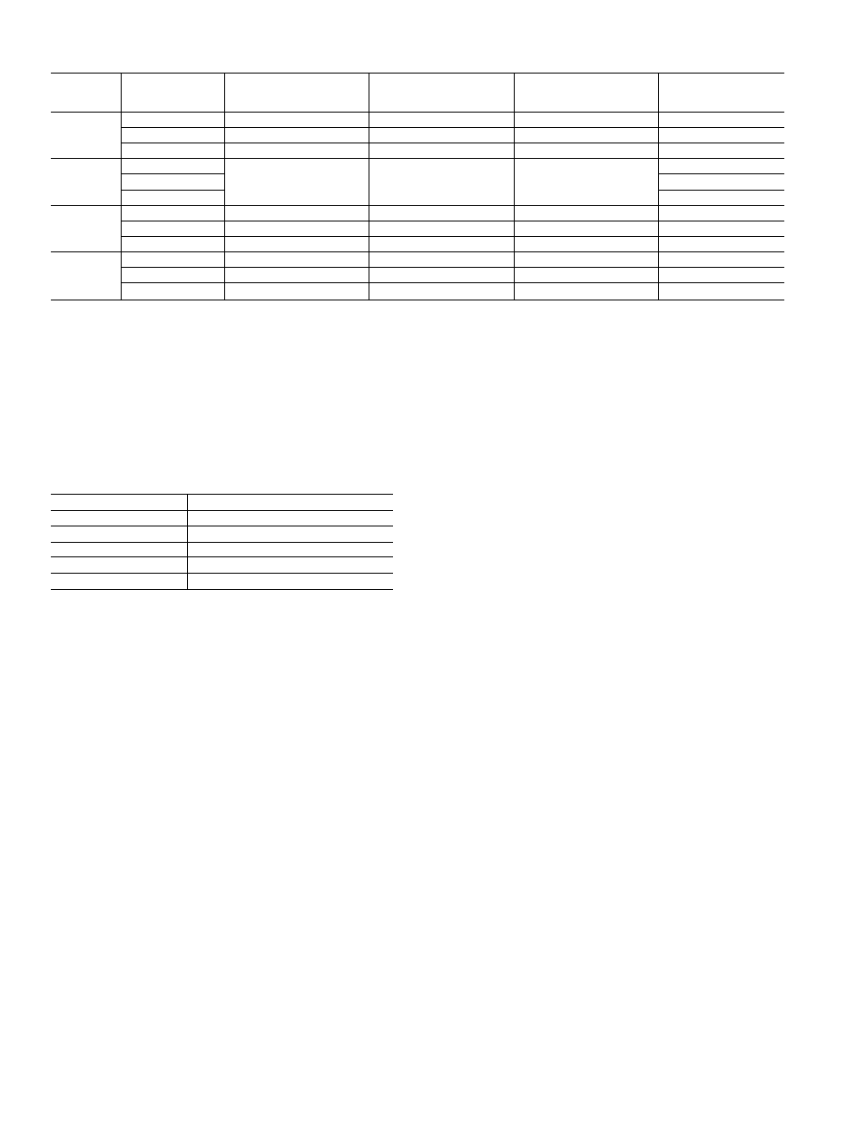
Table 25 — Evaporator-Fan Motor Data
UNIT
48TJ
UNIT
VOLTAGE
MAXIMUM
ACCEPTABLE
CONTINUOUS ВНР*
MAXIMUM
ACCEPTABLE
CONTINUOUS BkW*
MAXIMUM
ACCEPTABLE
OPERATING WATTS
MAXIMUM
AMP DRAW
016
208/230
4.25
3.17
3,775
10.5
460
4.25
3.17
3,775
4.8
575
3.45
2.59
3,065
3,9
020
208/230
5.90
4.40
5,180
15.8
460
7.9
575
6,0
024
208/230
8.70
6.49
7,915
22.0
460
9.50
7.08
8,640
13.0
575
8.70
6.49
7,915
10.0
028
208/230
10.20
7.61
9,510
28.0
460
11.80
8.80
11,000
14.6
575
10.20
7.61
9,510
13.0
LEGEND
ВНР
— Brake Horsepower
BkW
— Brake Kilowatts
‘Extensive motor and eleclricai testing on these units ensures that the fuii horsepower (brake kiiowatt)
range of the motors can be utilized with confidence. Using your fan motors up to the horsepower (brake
kilowatt) ratings shown in this table will not result in nuisance tripping or premature motor failure. Unit
warranty will not be affected.
NOTE: All indoor-fan motors 5 hp and larger meet the minimum efficiency requirements as established by
the Energy Policy Act of 1992 (EPACT) effective October 24, 1997.
Table 26 — Evaporator-Fan Motor Efficiency
UNIT 48TJ
MOTOR EFFICIENCY (%)
016 (3.0 Hp)
81.7
016(3.7 Hp)
85,8
020 (5 Hp)
87.5
024 (7.5 Hp)
88.5
028 (10 Hp)
89,5
NOTE: All indoor-fan motors 5 hp and larger meet the minimum effi
ciency requirements as established by the Energy Policy Act of 1992
(EPACT) effective October 24, 1997.
CONDENSER-FANS AND MOTORS Condenser fans
and motor's are factoi-y set. Refer to Condenser-Fan Adjustment
section (page 42) as requii'ed. Be sure that tans I'otate in the
pixrper direction.
RETURN-AIR FILTERS — Check that coi'rect filter's ar'e
installed in filter tracks (see Table I). Do not oper'ate unit with
out retur n-air filter s.
OUTDOOR-AIR INLET SCREENS — Outdoor-air inlet
scr'eens must be in place befor'e oper'ating unit.
GAS HEAT — Ver'ify gas pr'essures befor'e tur'ning on heat as
follows:
1. Turn off r"nanual gas stop.
2. Connect pr'essur'e gage to supply gas pressure tap (see
Fig. 1.3).
3. Connect pressur'e gage to r'nanifold pr'essur'e tap on gas
valve.
4. Turn on ruanual gas stop and set theranostat to HEAT
position. Adjust set point to several degr'ees above the
curr'ent r'oom teruper'atun; to ensur'e a heat demand. After
the unit has tarn for several minutes, verify that incoming
pressure is 5.5 in. wg or gr'eater', and that the manifold
pressure is 3.3 in. wg. If manifold pr'essure must be ad
justed, refer to Gas Valve Adjustment section on page 43.
.3. After unit has been in oper ation for 5 minutes, check tem
perature rise acr'oss the heat exchangers. See unit infor'-
rnative plate for corr'ect rise limits of the heat supplied.
Air quantities may need to be adjusted to bring the actual
rise to within the allowable limits.
Operating Sequence
COOLING, UNITS WITHOUT ECONOMIZER — Wlien
ther'rnostat calls for cooling, ter'rnimils G and Y1 ar'e ener'gized.
The indoor (evaporator') fan contactor (IFC), cornpr'essor con
tactor no. 1 (Cl) and outdoor'-fan contactor (OFC) an: ener'
gized, and evapor'ator-fan motor', cornpnsssor' no. 1, and both
condenser' fans star!. Tlie condenser'-fan motor's rirn continuous
ly while unit is cooling. If the thermostat calls for a second stage
of cooling by ener'gizing Y2, cornpr'essor contactor no. 2 (C2) is
energized and compressor no. 2 starts.
When the thermostat is satisfied, Cl and C2 ше deener
gized and tlie cornpr'essors and outdoor (condenser) fan motors
(OFM) shut off. After a 30-second delay, the indoor (evapora
tor') fan motor (IFM) shuts off If the ther'rnostat fan selector
switch is in the ON position, tlie evapor'ator-fan motor will ran
continuously.
HEATING. UNITS WITHOUT ECONOMIZER ^ When
the thermostat calls for heating, ter'rninal W1 is ener'gized. In
or'der to pr'event ther'rnostat shorf-cycling, the unit is locked
into the Heating mode for at least 1 minute when W1 is ener'
gized. The induced-dr'aft motor (IDM) is then ener'gized and
the bur'ner ignition sequence begins. The indoor (evapor'ator')
fan motor (IFM) is ener'gized 4.5 seconds after a flame is
ignited. On units equipped for two stages of heat, when addi
tional heat is needed, W2 is energized and the high-fu'e sole
noid on the main gas valve (MGV) is ener'gized. When the
ther'rnostat is satisfied and W1 and W2 ar'e deener'gized, the
IFM stops after a 4.5-second tirne-off delay.
COOLING. UNITS WITH ECONOMI$ERIV ^ When tree
cooling is not available, tlie compressor's will be controlled by
the zone thermostat. When tree cooling is available, the
outdoor-itir damper is modulated by the EconoMi$er'IV contr'ol
to pr'ovide a .50 to 55 F supply-air temperature into the zone. As
the supply-air ternper'ature fluctuates above 55 or below 50 F,
the damper's will be modulated (open or close) to br'ing the
supply-air ternperatun: back within the set point limits.
For EconoMi$er'IV oper'ation, there must be a ther'rnostat
call for the fan (G). This will move Ше damper to its minimum
position during the occupied mode.
.36