Economiserlv component locations ■ side view – Carrier 48TJ016-028 User Manual
Page 23
Attention! The text in this document has been recognized automatically. To view the original document, you can use the "Original mode".
OPTIONAL ECONOMISER!V AND ECONOMISER2 —
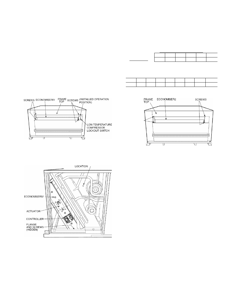
See Fig. 32 and 33 for EconoMiSerlV component locations.
See Fig. 34 for EconoMi$er2 component locations.
NOTE: These instinctions are for installing the optional
EconoMiSerlV and EconoMi$er2 only. Refer to the accessory
EconoMiSerlV or EconoMi$er2 installation instaictions when
field installing an EconoMiSerlV orEconoMi$er2 accessory.
To complete instiillation of the optional EconoMiSerlV, per
form the following procedure.
1. Remove the EconoMiSerlV hood. Refer to Step 11 — In
stall Outdoor-Air Hood on page 14 for infonnation on
removing and installing the outdoor-iiir hood.
2. Relocate outdoor air temperature sensor from shipping
position to operation position on EconoMiSerlV. See
Fig. 32.
IMPORTANT: F;iilure to relocate the sensor will result in
the EconoMiSerlV not operating properly.
3. Reinstall economizer hood.
4. Install till EconoMiSerlV accessories. EconoMiSerlV
wiring is shown in Fig. 35. EconoMiSer2 wiring is shown
in Fig. 36.
Outdoor air leakage is shown in Table 9. Return £iir pressure
di'op is shown in Table 10.
Table 9 — Outdoor Air Damper Leakage
LEAKAGE (cfm)
DAMPER STATIC PRESSURE (in. wg)
0.2
0.4
0.6
0.8
1.0
1.2
35
53
65
75
90
102
Table 10 — Return Air Pressure Drop (In. wg)
CFM
4500
5000
5400
6000
7200
7500
9000
10,000
11,250
0.040 0.050
0.060 0.070 0.090
0.100 0.110
0.120
0.140
OUTDOOR AIR
TEMPERATURE SENSOR
Fig. 32 — EconoMiSerlV Component Locations ■
End View
SCREWS
Fig. 34 — EconoMISer2 Component Locations
SUPPLY AIR
TEMPERATURE SENSOR
Fig. 33
EconoMiSerlV Component Locations ■
Side View
23