Carrier 48TJ016-028 User Manual
Page 22
Attention! The text in this document has been recognized automatically. To view the original document, you can use the "Original mode".
Enthalpy Sensor Jumper Settings — There iii'e two jumpers.
One jumper determines the mode of the enthalpy sensor. The
otlier jumper is not used. To access the jumpers, remove the
4 screws holding the cover on the enthalpy sensor and then re
move the cover. The factory settings for the iumpers are M.3
and OFF.
Tlie mode jumper should be set to M.3 for 4 to 20 mA
output. Tlie factoiy test jumper should remain on OFF or the
enthalpy sensor will not calculate enthiilpy.
ENTHALPY SENSORS AND CONTROL The enthalpy
control (HH57AC077) is supplied as a field-installed accessoiy
to be used with the EconoMi$er2 damper control option. The
outdoor air enthalpy sensor is part of the enthalpy control. The
separate field-installed accessoiy return air enthalpy sensor
(HH57AC078) is required for differential enthalpy control.
NOTE: Tlie entlialpy control must be set to tire “D” setting for
differential entlialpy control to work properly.
Tlie enthalpy control receives tlie indoor and return
enthalpy from the outdoor and return air enthalpy sensoii; and
provides a diy contact switch input to the PremierLink'M
controller. Locate the controller in place of an existing econo
mizer controller or near the actuator. The mounting plate may
not be needed if existing bracket is used.
A closed contact indicates that outside air is preferred to the
return air. An open contact indicates that the economizer
should remain at minimum position.
Outdoor
Air
Enthalpy
Sensor/Enthalpv
Controller
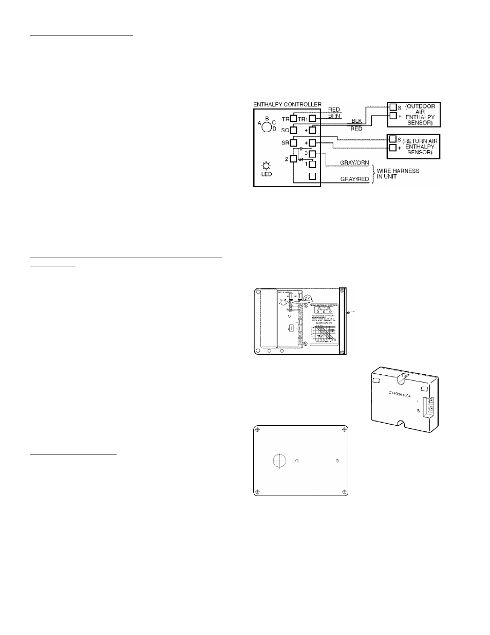
(HH57AC077) — To wire the outdoor air enthalpy sensor,
perform the following (see Eig. .30 and .31):
NOTE: The outdoor air sensor can be removed from the back
of the enthiilpy controller and mounted remotely.
1, Lise a 4-conductor, 18 or 20 AWG cable to connect the
enthalpy control to the PremierLink controller and power
transformer.
2. Connect the following 4 wires from the wire hiu'ness
located in rooftop unit to the enthalpy controller:
a. Connect the BRN wire to the 24 vac terminal (TRl)
on enthalpy control and to pin 1 on 12-pin harness.
b. Connect the RED wire to the 24 vac GND terminal
(TR) on enthalpy sensor and to pin 4 on 12-pin
harness.
c. Connect the GRAY/ORN wire to J4-2 on Premier
Link controller and to terminal (.3) on enthalpy
sensor.
d. Connect the GRAY/RED wire to J4-1 on Premier
Link controller and to terminal (2) on enthalpy sensor.
NOTE: If installing in a Canier rooftop, use the two gray wires
provided from the control section to the economizer to connect
PremierLink controller to terminals 2 and 3 on enthiilpy sensor.
Return Air Enthalpy Sensor — Mount the return-air enthalpy
sensor (HH57AC078) in the return-air duct. Tlie return air
sensor is wired to the enthalpy controller (HH57AC077). The
outdoor enthiilpy changeover set point is set at the controller.
To wire the return air enthalpy sensor, perform the follow
ing (see Fig. 30):
1, Use a 2-conductor, 18 or 20 AWG, twisted pair cable to
connect the return air enthalpy sensor to the enthalpy
controller.
At the enthalpy control remove the factoiy-installed
resistor from the (SR) and
(-I-)
terminals.
Connect the field-supplied RED wire to (-I-) spade
connector on the return air enthalpy sensor and the (SR-i-)
terminal on the enthalpy controller. Connect the BLK
wire to (S) spade connector on the return air enthalpy
sensor and the (SR) terminal on the enthalpy controller.
NOTES:
1. Remove factory-installed jumper across SR and + before con
necting wires from return air sensor.
2. Switches shown in high outdoor air enthalpy state. Terminals 2
and 3 close on low outdoor air enthalpy relative to indoor air
enthalpy.
3. Remove sensor mounted on back of control and locate in out
side airstream.
Fig. 30 — Outdoor and Return Air Sensor Wiring
Connections for Differential Enthalpy Control
-BRACKET
HH57AC077
ENTHALPY
CONTROL AND
OUTDOOR AIR
ENTHALPY SENSOR
HH57AC078 ENTHALPY
SENSOR (USED WITH
ENTHALPY CONTROL
FOR DIFFERENTIAL
ENTHALPY OPERATION)
MOUNTING PLATE
Fig. 31 — Differential Enthalpy Control,
Sensor and Mounting Plate (33AMKITENT006)
22