Step 13 — adjust factory-installed options, Fig. 24 — premierlink controller – Carrier 48TJ016-028 User Manual
Page 17
Attention! The text in this document has been recognized automatically. To view the original document, you can use the "Original mode".
step 13 — Adjust Factory-Installed Options
PREMIERLINKTM CONTROL — The PremierLink control
ler is available as a special order from the factoiy and is com
patible with the CiU'rier Comfort Network® (CCN) system.
This control is designed to allow usere the access and ability to
change factoiy-defmed settings, thus expanding the function of
the standard unit control board. Carrier’s diagnostic standard
tier display tools such as Navigator''^' device or Scrolling
Marquee can be used witli the PremierLink controller.
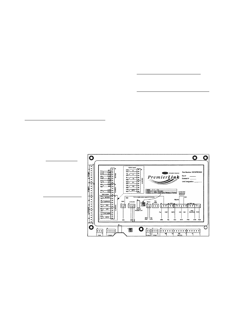
Tire PremierLink controller (see Fig. 24) requires the use of
a Cai'rier electronic themnostat or a CCN connection for time
broadcast to initiate its internal timeclock. This is necessaiy for
broadcast of time of day functions (occupied/unoccupied). No
sensors are supplied with the field-mounted PremierLink con
trol. The factoiy-installed PremierLink conti'ol includes only
the supply-air temperature (SAT) sensor and the outdoor air
temperature (OAT) sensor as standiu'd. An indoor air quality
(CO
2
) sensor can be added as an option. Refer to Table 8 for
sensor usage. Refer to Fig. 25 for PremierLink controller wir
ing. The PremierLink control may be mounted in the control
panel or an area below the control panel.
NOTE: PremierLink controller version 1.3 and later is shipped
in Sensor mode. If used with a thermostat, the PremierLink
controller must be configured to Thermostat mode.
Install the Supply Air Temperature (SAT) Sensor — When
the unit is supplied with a factoiy-mounted PremierLink con
trol, the supply-air temperature (SAT) sensor (33ZCSENSAT)
is factoiy-supplied and wired. The wiring is routed from the
PremierLink control over the control box, through a grommet.
into the fan section, down along the back side of the fan, and
along the fan deck over to the supply-air opening.
The SAT probe is wire-tied to tire supply-air opening (on the
horizontal opening end) in its shipping position. Remove the
sensor for installation. Re-position the sensor in the flange of
tire supply-air opening or in the supply air duct (as required by
local codes). Drill or punch a ‘/
2
-in. hole in the flange or duct.
Use two field-supplied, self-drilling screws to secure the sensor
probe in a horizontal orientation.
NOTE: The sensor must be mounted in tire dischiu'ge airstream
downstream of the cooling coil and any heating devices. Be
sure the probe tip does not come in contact with any of the unit
or heat surfaces.
Outdoor Air Temperature (OAT) Sensor — When the unit is
supplied with a factoiy-mounted PremierLink control, the
outdoor-air temperature sensor (OAT) is factoiy-supplied and
wired.
Install the Indoor Air Quality (CQ
t
) Sensor — Mount the
optional indoor air quality (CO
2
) sensor according to manufac
turer specificiitions.
A sepiii'ate field-supplied transformer must be used to
power the CO
2
sensor.
Wire the CO
2
sensor to tlie COM and lAQI terminals of J5
on the PremierLink controller. Refer to the PremierLink Instal
lation, Start-up, and Configuration Instnictions for detailed
wiring and configuration information.
HVAC SENSOR INPUTS
SPACE TEMP
SET POINT ^
SUPPLY AIR TEMP
OUTDOOR TEMP
INDOOR AIR QUALITY
OUTDOOR AIR QUALITY
DUAL MODE SENSOR (STAT)
REMOTE OCCUPANCY (Q)
COMP SAFETY (Y1) ^
FIRE SHUTDOWN (Y2) ^
SUPPLY FAN STATUS (W1)
NOT USED (W2) ^
ENTHALPY STATUS (ENTH)
/
CCN/LEN
PORT
NAVIGATOR
PORT
X f M N N
4
-
2
OMA
INDOOR COMPR HEAT EXHAUST
ECONOMIZER FAN MOTOR 1&2 LOW/HIGH RVS VALVE
------------------------------- OUTPUTS--------------------------------------------•-
Fig. 24 — PremierLink Controller
17