Step 12 — install all accessories— install all, A caution, Fig. 22 — motormaster i sensor locations – Carrier 48TJ016-028 User Manual
Page 15: Step 12 — install all accessories, Fig. 21 — wind baffle details
Attention! The text in this document has been recognized automatically. To view the original document, you can use the "Original mode".
step 12 — Install All Accessories
— install all
field-installed accessories. Refer to the accessoiy installation
instructions included with each accessoiy.
MOTORMASTER® I CONTROL INSTALLATION
(48TJ0I6,020 UNITS)
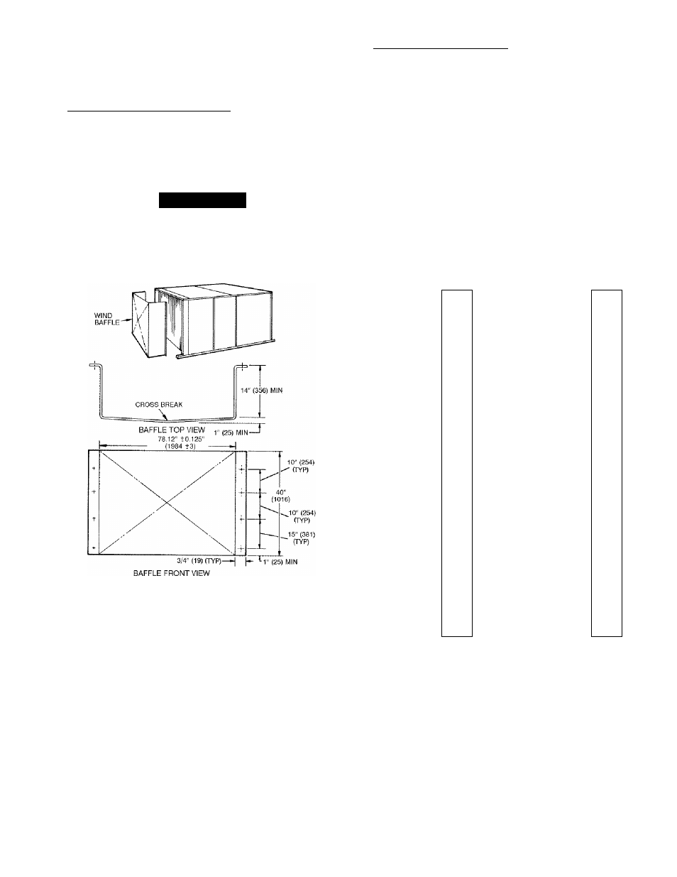
Install Field-Fabricated Wind Baffles — Wind baffles must
be field-fabricated for all units to ensure proper cooling cycle
operation at low ambient temperatures. See Fig. 21 for baffle
detiiils. Use 20-gage, galvanized sheet metal, or similar
coiTosion-resistant metal for baffles. Use field-supplied screws
to attach baffles to unit. Screws should be V
4
-in. diameter and
5/8-in. long. Drill required screw holes for mounting baffles.
A CAUTION
To avoid diunage to the refrigerant coils and electrical com
ponents, use recommended screw sizes only. Use care
when drilling holes.
Install Motormaster I Controls — Only one Motormaster I
control is required per unit. Tlie Motormaster I control must be
used in conjunction with the Accessoiy 0° F Low Ambient Kit
(purchased separately). Tlie Motonnaster I device controls out
door fan no. I while outdoor fans no. 2 and ."5 are sequenced off
by the Accessoiy 0° F Low Ambient Kit.
Accessory 0° F Low Ambient Kit — Instiill the Accessoiy 0° F
Low Ambient Kit per instmction supplied with accessoiy.
Sensor Assembly — Install the sensor assembly in the location
shown in Fig. 22.
Motor Mount — To ensure proper fan height, replace the exist
ing motor mount with the new motor mount provided with
accessoiy.
Transformer (460 and 575-v Units Only) — On 460 and 575-v
units, a transfonner is required. The transformer is provided
with the accessoiy and must be field-installed.
Motormaster I Control — Recommended mounting location is
on the inside of the panel to the left of the control box. The
control should be mounted on the inside of the panel, verti
cally, with leads protniding from bottom of extinsion.
NOTE: Dimensions in ( ) are in mm.
Fig. 21 — Wind Baffle Details
SENSOR -
LOCATION
0
о о ° o
0
0
ï h -
cp o
0
0
cp
o
i h "
cp o
î i ° °
i l »
cp
0
(b 0
cp
0
i l »
cp
0
0 0
cp
0
i l »
G )
o
d )
o
cp o
i l "
G )
o
cp o
i l »
® 0
d >
0
tp 0
i l »
0
о о °
0
d >
0
cp
0
i l »
(p 0
Î0 0
cp
0
i l »
(p
0
cp
0
i l »
cp
0
tp 0
i l »
cp o
SENSOR ----------
cp o
© 0
LOCATION
i l »
G) 0
î i “ °
è
0
cp
0
i l »
G) 0
0 0
cp
0
i l »
G )
o
© o
cp o
i l »
G )
o
î i ° °
cp o
i l »
cp
0
о о ° o
cb 0
tp 0
i l »
0
î i ° °
0
0
cp
0
i l »
HAiRPIN END
48TJ016
HAIRPIN END
48TJ020
NOTE: All sensors are located on the eighth hairpin up from the
bottom.
Fig. 22 — Motormaster I Sensor Locations
15