Winco DSE71xx Series User Manual
Page 7
DSE Model 71xx Series Control & Instrumentation System Mk2 Operators Manual
Part No. 057-113 71xx Series OPERATING MANUAL ISSUE 2 12/08/2010 ADM
7
3.1
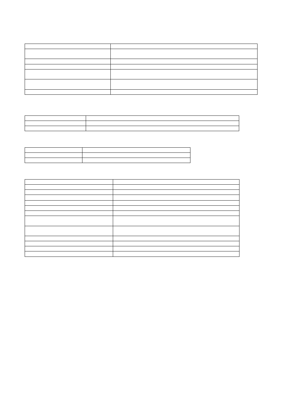
POWER SUPPLY REQUIREMENTS
Minimum supply voltage
8V continuous
Cranking dropouts
Able to survive 0V for 50mS providing the supply was at least 10V before
the dropout and recovers to 5V afterwards.
Maximum supply voltage
35V continuous (60V protection)
Reverse polarity protection
-35V continuous
Maximum operating current
(all inputs and sensor active)
146mA at 12V, 79mA at 24V
Nominal standby current
(no inputs active)
72mA at 12V, 42mA at 24V
Power Save Mode Active
43mA at 12V, 28mA at 24V
Plant supply instrumentation display
Range
0V-60V DC (note Maximum continuous operating voltage of 35V DC)
Resolution
0.1V
Accuracy
1% full scale
3.2
TERMINAL SPECIFICATION
Connection type
Screw terminal, rising clamp, no internal spring
Min cable size
0.5mm² (AWG 24)
Max cable size
2.5mm² (AWG 10)
3.3
GENERATOR VOLTAGE / FREQUENCY SENSING
Measurement type
True RMS conversion
Sample Rate
5KHz or better
Harmonics
Up to 11
th
or better
Input Impedance
300K
Ω
ph-N
Phase to Neutral
15V to 333V AC (max)
Phase to Phase
25V to 576V AC (max)
Common mode offset from Earth
100V AC (max)
Resolution
1V AC phase to neutral
2V AC phase to phase
Accuracy
±1% of full scale phase to neutral
±2% of full scale phase to phase
Minimum frequency
3.5Hz
Maximum frequency
75.0Hz
Frequency resolution
0.1Hz
Frequency accuracy
±0.2Hz