Winco DSE71xx Series User Manual
Page 10
DSE Model 71xx Series Control & Instrumentation System Mk2 Operators Manual
10
Part No. 057-113 71xx Series OPERATING MANUAL ISSUE 2 12/08/2010 ADM
3.8
DIMENSIONS AND MOUNTING
3.8.1
DIMENSIONS
240.0mm x 181.1mm x 41.7mm
(9.4” x 7.1” x 1.6”)
3.8.2
PANEL CUTOUT
220mm x 160mm
(8.7” x 6.3”)
3.8.3
WEIGHT
0.7kg
(1.4lb)
3.8.4
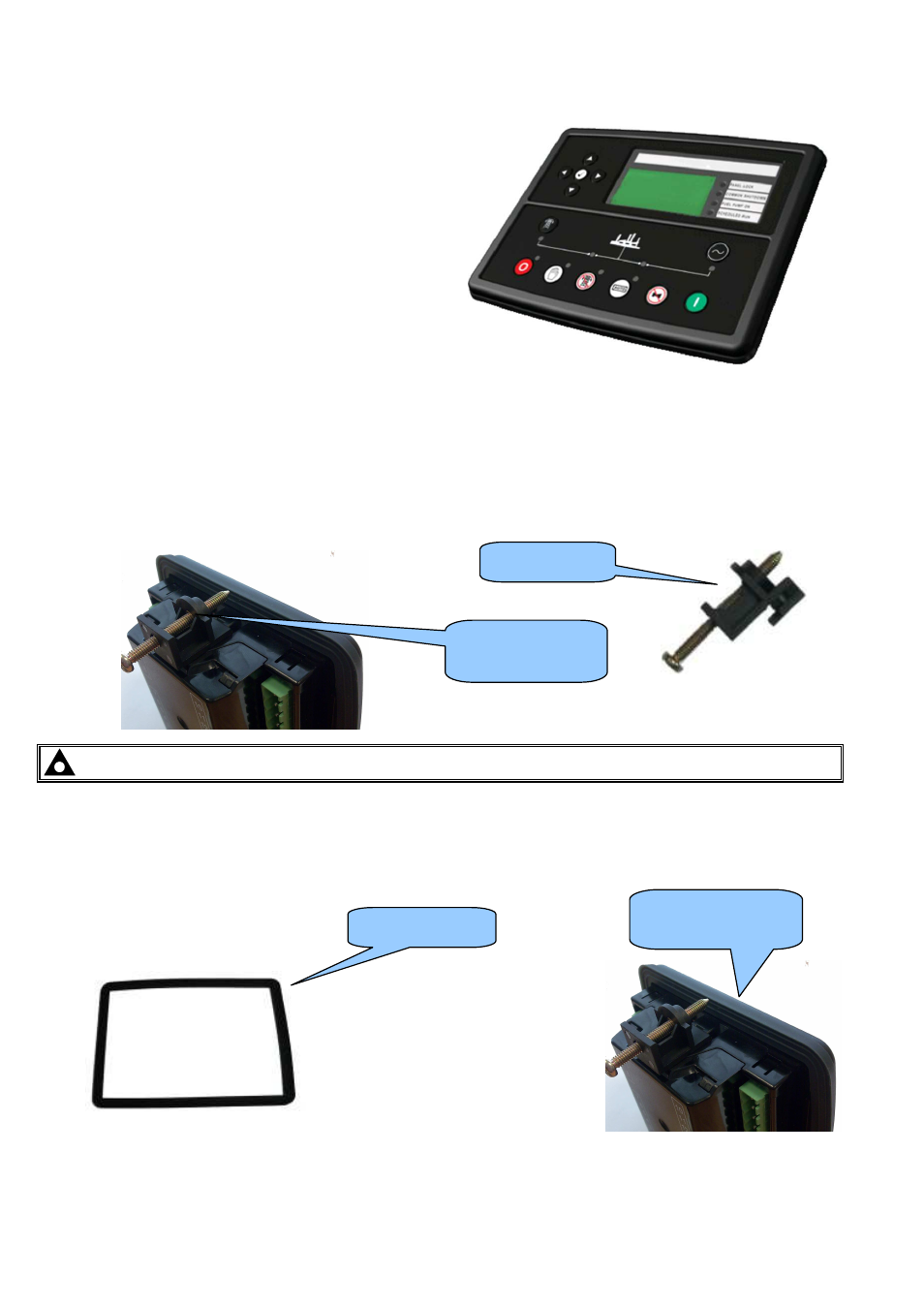
FIXING CLIPS
The supplied fixing clips hold the module into the panel fascia.
•
Withdraw the fixing clip screw (turn anticlockwise) until only the pointed end is protruding from the clip.
•
Insert the three ‘prongs’ of the fixing clip into the slots in the side of the 71xx series module case.
•
Pull the fixing clip backwards (towards the back of the module) ensuring all three prongs of the clip are inside their
allotted slots.
•
Turn the fixing clip screws clockwise until they make contact with the panel fascia.
•
Turn the screws a little more to secure the module into the panel fascia. Care should be taken not to over tighten the
fixing clip screws.
NOTE:- In conditions of excessive vibration, mount the panel on suitable anti-vibration mountings.
3.8.5
OPTIONAL SILICON SEALING GASKET
The optional silicon gasket provides improved sealing between the 71xx series module and the panel fascia.
The gasket is fitted to the module before installation into the panel fascia.
Take care to ensure the gasket is correctly fitted to the module to maintain the integrity of the seal.
Fixing clip fitted to
module
Fixing clip
Gasket fitted to
module
Sealing gasket