4installation, 1 terminal description, 1 dc supply, fuel and start outputs – Winco DSE71xx Series User Manual
Page 12
DSE Model 71xx Series Control & Instrumentation System Mk2 Operators Manual
12
Part No. 057-113 71xx Series OPERATING MANUAL ISSUE 2 12/08/2010 ADM
4
INSTALLATION
The DSE71xx Series module is designed to be mounted on the panel fascia. For dimension and mounting details, see the
section entitled Specification, Dimension and mounting elsewhere in this document.
4.1 TERMINAL DESCRIPTION
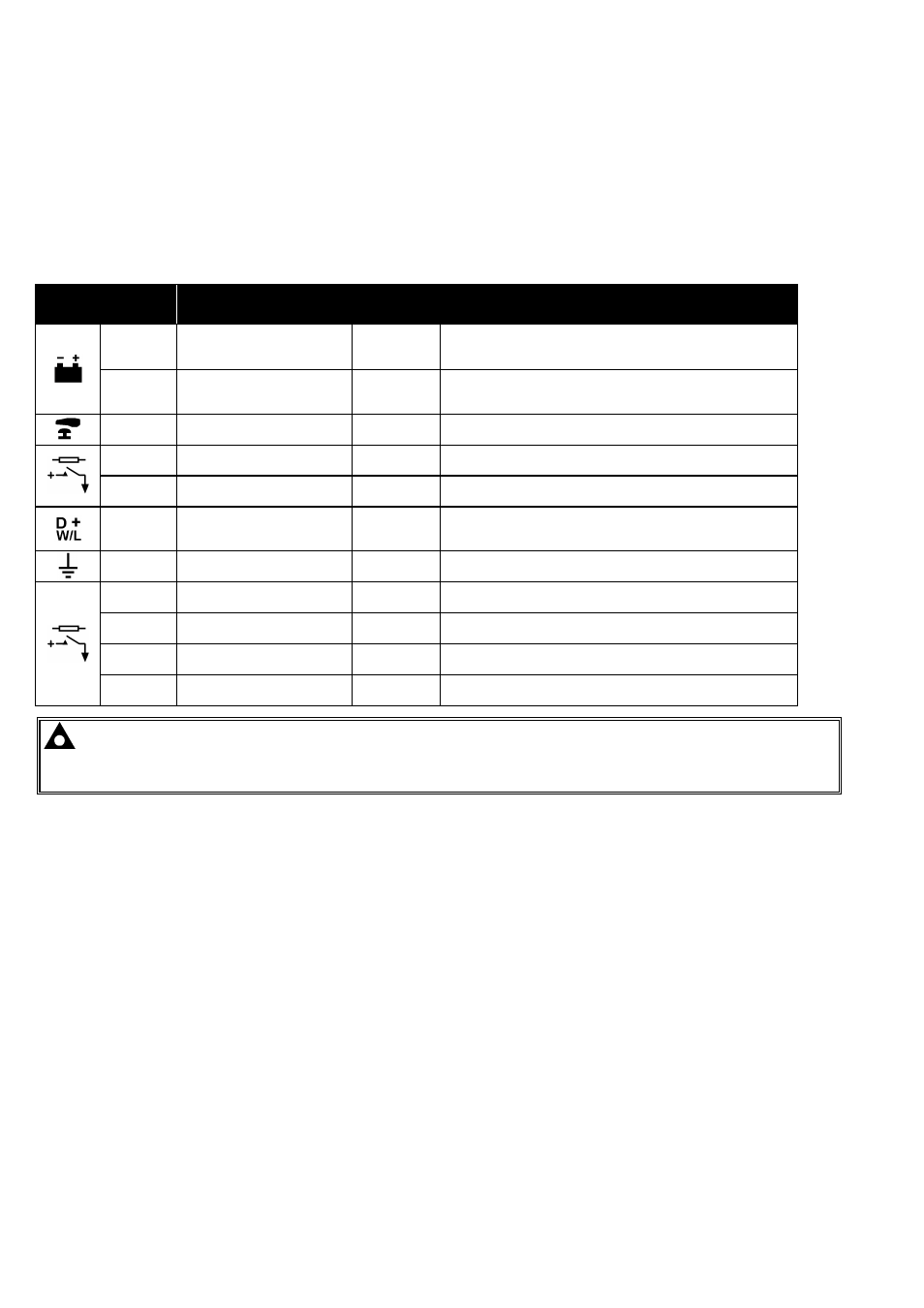
4.1.1 DC SUPPLY, FUEL AND START OUTPUTS
PIN No
DESCRIPTION
CABLE
SIZE
NOTES
1
DC Plant Supply Input
(Negative)
2.5mm²
AWG 13
2
DC Plant Supply Input
(Positive)
2.5 mm²
AWG 13
(Recommended Maximum Fuse 15A anti-surge)
Supplies the module (2A anti-surge requirement) and all
output relays
3
Emergency Stop
1.0mm²
AWG 18
Plant Supply Positive from terminal 2. 3 Amp rated.
4
Output A
1.0mm²
AWG 18
Plant Supply Positive from terminal 2. 3 Amp rated.
Normally used for FUEL control.
5
Output B
1.0mm²
AWG 18
Plant Supply Positive from terminal 2. 3 Amp rated.
Normally used for START control.
6
Charge fail / excite
2.5mm²
AWG 13
Do not connect to ground (battery negative).
If charge alternator is not fitted, leave this terminal
disconnected.
7
System Eartth
1.0mm²
AWG 18
8
Output C
1.0mm²
AWG 18
Plant Supply Positive from terminal 2. 3 Amp rated.
Normally used for Generator load switch control.
9
Output D
1.0mm²
AWG 18
Plant Supply Positive from terminal 2. 3 Amp rated.
Normally used for Mains load switch control (DSE7120)
10
Output E
1.0mm²
AWG 18
Plant Supply Positive from terminal 2. 3 Amp rated.
11
Output F
1.0mm²
AWG 18
Plant Supply Positive from terminal 2. 3 Amp rated.
NOTE:- When the module is configured for operation with an electronic engine, FUEL and START
output requirements may be different. Refer to Electronic Engines and DSE Wiring for further information.
DSE Part No. 057-004.