Winco DSE71xx Series User Manual
Page 16
DSE Model 71xx Series Control & Instrumentation System Mk2 Operators Manual
16
Part No. 057-113 71xx Series OPERATING MANUAL ISSUE 2 12/08/2010 ADM
4.1.8 DIGITAL INPUTS
PIN
No
DESCRIPTION
CABLE
SIZE
NOTES
60
Configurable digital input A
0.5mm²
AWG 20
Switch to negative
61
Configurable digital input B
0.5mm²
AWG 20
Switch to negative
62
Configurable digital input C
0.5mm²
AWG 20
Switch to negative
63
Configurable digital input D
0.5mm²
AWG 20
Switch to negative
NOTE:- Terminals 64 to 69 are not fitted to the DSE7100 series controller
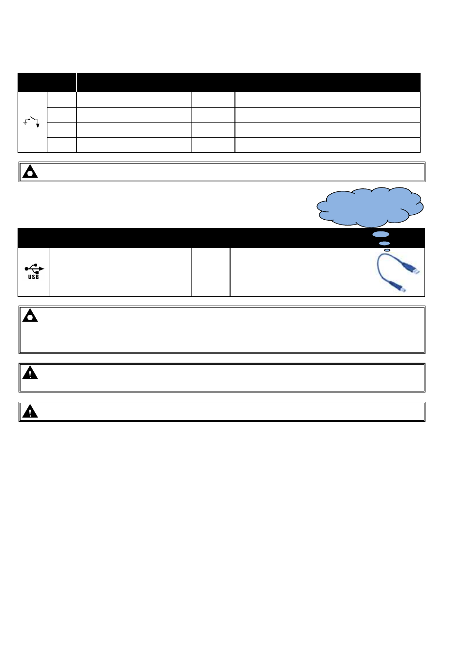
4.1.9 PC CONFIGURATION INTERFACE CONNECTOR
DESCRIPTION
CABLE
SIZE
NOTES
Socket for connection to PC with DSE
Configuration Suite PC software.
0.5mm²
AWG 20
This is a standard USB type A to
type B cable.
NOTE:- The USB connection cable between the PC and the 7100 series module must not be extended
beyond 5m (5yds). For distances over 5m, it is possible to use a third party USB extender. Typically, they
extend USB up to 50m (yds). The supply and support of this type of equipment is outside the scope of
Deep Sea Electronics PLC.
CAUTION!: Care must be taken not to overload the PCs USB system by connecting more than the
recommended number of USB devices to the PC. For further information, consult your PC supplier.
CAUTION!: This socket must not be used for any other purpose.
This configuration cable is
the same as normally used
between a PC and a USB
printer.