7module display, 1 backlight, 2 graphical display – Winco DSE71xx Series User Manual
Page 28
DSE Model 71xx Series Control & Instrumentation System Mk2 Operators Manual
28
Part No. 057-113 71xx Series OPERATING MANUAL ISSUE 2 12/08/2010 ADM
7
MODULE DISPLAY
7.1
BACKLIGHT
The backlight will be on if the unit has sufficient voltage on the power connection while the unit is turned on, unless the unit is in
Power Save mode, or if the engine is cranking for which the backlight will be turned off.
7.2
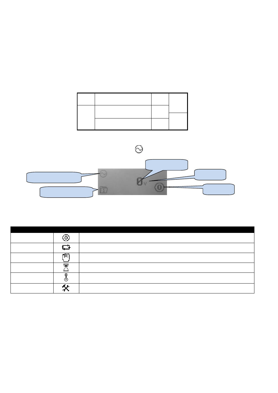
GRAPHICAL DISPLAY
A 48x132 pixel LCD is used for the display. The display is segmented into areas for instrumentation, units, alarm icons and
various other icons.
Inst.
Icon
Instrumentation
Units
Alarm
Icon
Active
config
/FPE,
event
index
Instrumentation
Units
Mode
Icon
Instrumentation
Units
7.2.1
DISPLAY EXAMPLE
This example shows Generator Volts as shown by the Generator
symbol.
7.2.2
MODE ICON
An icon is displayed in the mode icon area of the display to indicate what mode the unit is currently in.
Icon
Graphic
Details
Stopped
Appears when the engine is at rest and the unit is in stop mode.
Auto
Appears when the engine is at rest and the unit is in auto mode.
Manual
Appears when the engine is at rest and the unit is in manual mode/
Timer animation
Appears when a timer is active, for example cranking time, crank rest etc.
Running animation
Appears when the engine is running, and all timers have expired, either on or off load. The animation
rate is reduced when running in idle mode.
Front panel editor
Appears when the unit is in the front panel editor.
Mode Icon
Units
Instrumentation
Instrumentation Icon
Active configuration