Vt8300 series user interface guide, Parameter details, Setpoint adjustment for heating mode – Viconics VT8300 Low Voltage User Interface Guide User Manual
Page 36
36
Viconics Technologies Inc.
|
9245 Langelier Blvd.
|
St.-Leonard
|
Quebec
|
Canada
|
H1P 3K9
|
Tel: (514) 321-5660
|
Fax: (514) 321-4150
028-0427-01
www.viconics.com
|
November 2014
©
2
01
4 V
ic
onic
s T
ec
hno
lo
gi
es
Inc
. A
ll r
ig
ht
s r
ese
rv
ed
.
VT8300 Series
User Interface Guide
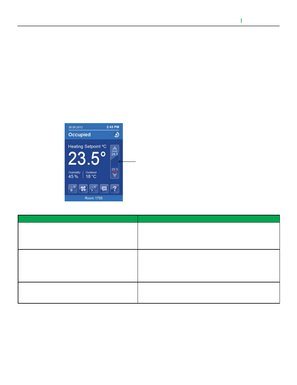
Setpoint Adjustment for Heating Mode
In automatic mode, setpoint showing at the top of the set point bar located directly under the blue line
represents the actual occupied cooling setpoint.
During occupied setpoints adjustment, large digits are temporarily used to display the occupied Cooling
Setpoint or occupied Heating Setpoint. The actual setpoint is dependent on the last effective demand (heating or
cooling). The setpoint on top of the red line represents the actual occupied heating setpoint. The
differential between the occupied heating and cooling setpoint is defined by the minimum deadband
configuration parameter.
Normal temperature display resumes after setpoints are adjusted and the actual occupied heating and cooling
setpoints show in the setpoint bar.
Automatic Heating/Cooling Mode
PARAMETER DETAILS
Configuration Parameters Default Value
Significance and Adjustments
Color
Default value: White
Color
Select user HMI colour.
Choices: Green, Blue, Brown, and Grey.
Main display
Default value: White
Main Display
Select default value displayed on main display as temperature or set-
point.
Choices: Temperature or setpoint.
Standby screen
Default value: No
Standby Screen
Selecting Yes shows a custom image after 2 minutes with no user activ-
ity on the touch screen.