Figure 2, Figure 3 – Tuffy Security 274 User Manual
Page 5
Page 5 of 10 - 3/14/2011 – Rev10/15/2012
24. Install the Rubber Seal around the inside perimeter of the lid on the flat surface. (Fig 2)
FIGURE 2
25. Check the lock and latch operation on the Tuffy console.
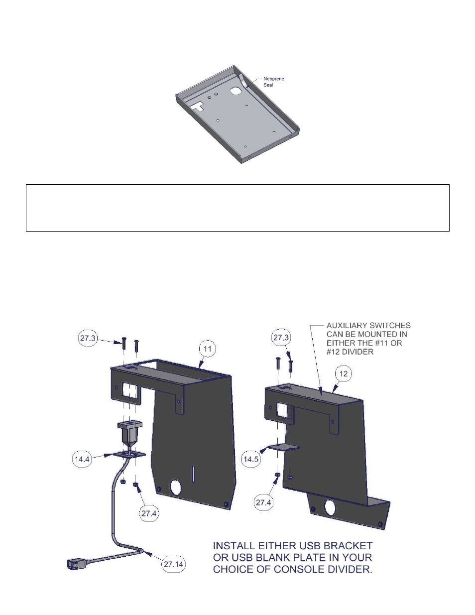
If the vehicle is equipped with console mounted USB port:
26. Install the USB port “pigtail” (#27.14 – Fig 3) through the #14.4 USB Port Mounting Plate and secure to the underside
of the #11 Electronics Mounting bracket or the #12 Divider bracket, as applicable, using the (2) #6-32x3/4” allen head
screws (#27.3) and (2) #6-32 nylock nuts (#27.4). Hand tighten. (Fig 3)
27. If not equipped with USB port, install the #14.5 USB Port Blank Cover plate to the underside of the #11 Electronics
Mounting bracket or the #12 Divider bracket, as applicable, using the (2) #6-32x3/4” allen head screws and (2) #6-32
nylock nuts. Hand tighten. (Fig 3)
28. If auxiliary switches will be mounted in either the #11 or #12 console divider, install them at this time. (See Fig 3)
29. If auxiliary switches will be mounted in the #14.2 or #14.3 Front Insert plates, install them at this time. (See Fig 5)
FIGURE 3